
Headset with ear cushion and means for limiting the compression of the cushion

Inactive Publication Date: 2004-06-08
NCT GROUP
View PDF20 Cites 21 Cited by
  • Summary
  • Abstract
  • Description
  • Claims
  • Application Information

AI Technical Summary

Benefits of technology

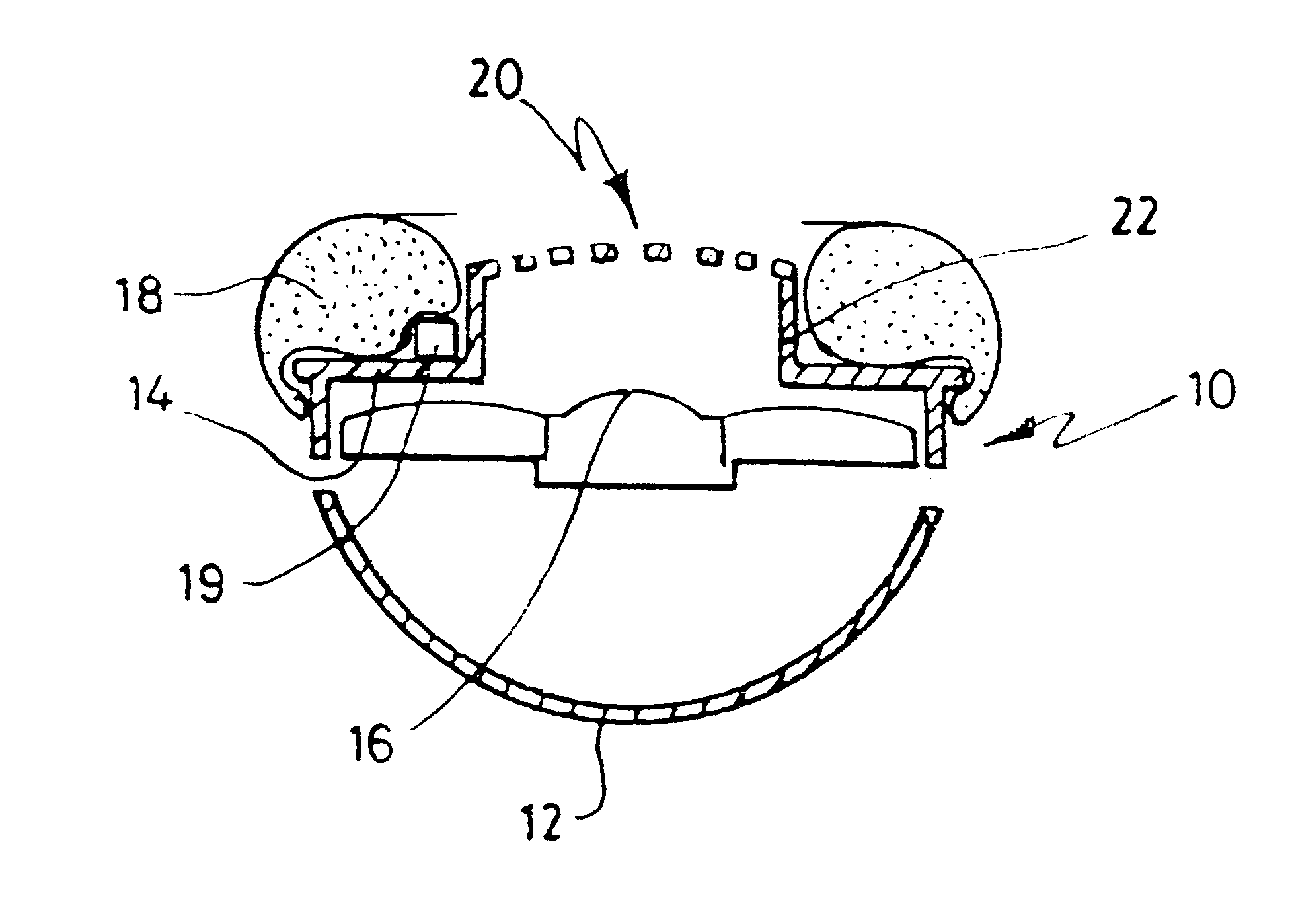
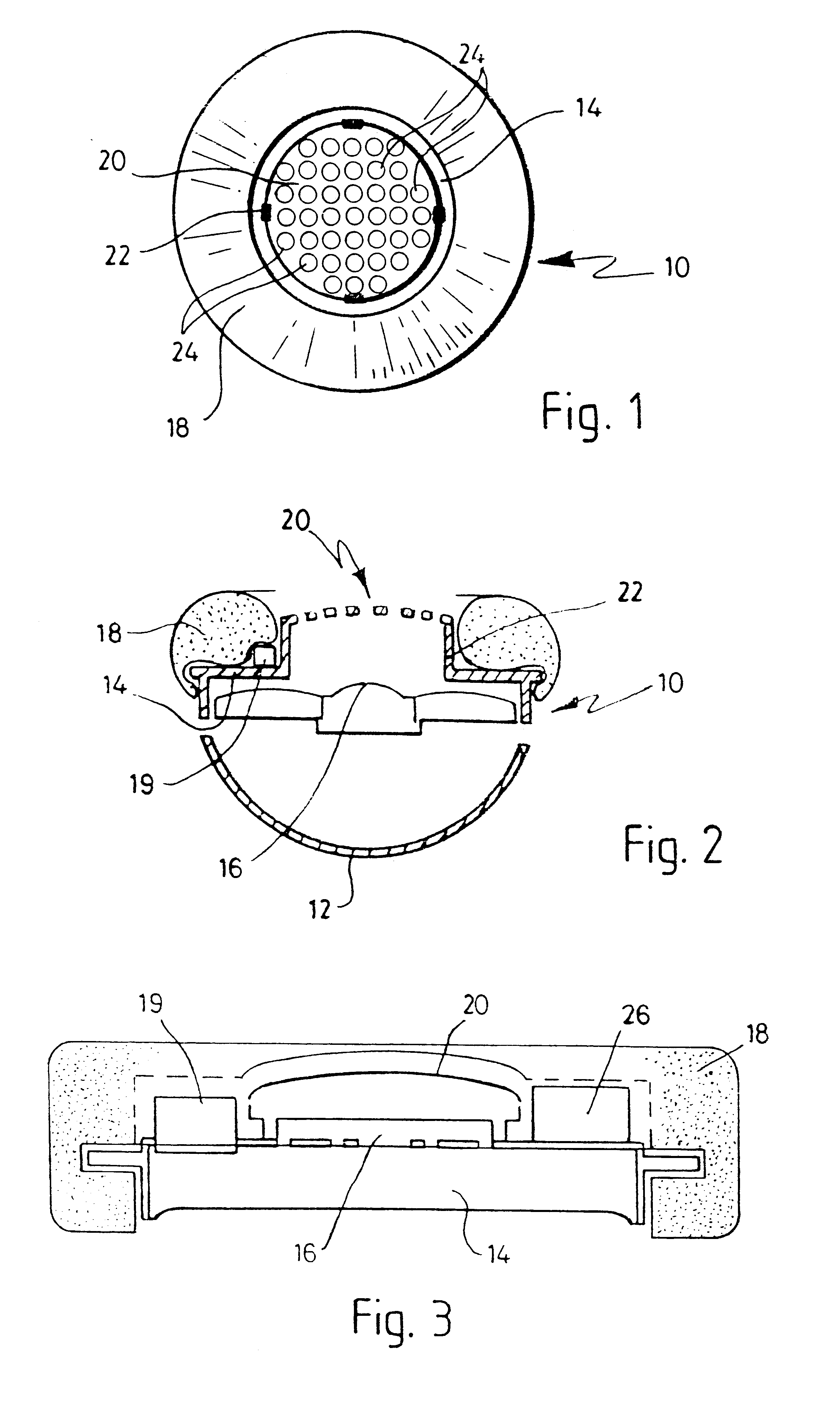
When the headset is receiving music or other sound, for example from a vehicle entertainment system, compression of the earpiece cushion is restricted to minimise distortion if the cushion is compressed, for example because the user presses by hand on the earpiece or leans his or her head against a pillow.
means for restricting compression of the cushion against the ear to the extent necessary substantially to prevent acoustic gain increasing beyond a threshold which gives rise to the generation of sound oscillations at the earpiece.
Moreover, the headset may include cushion deforming means for causing the cushion, when held against the ear, to close any gap which would otherwise exist between the side of the head and the front of the ear forwardly of and above the ear canal.
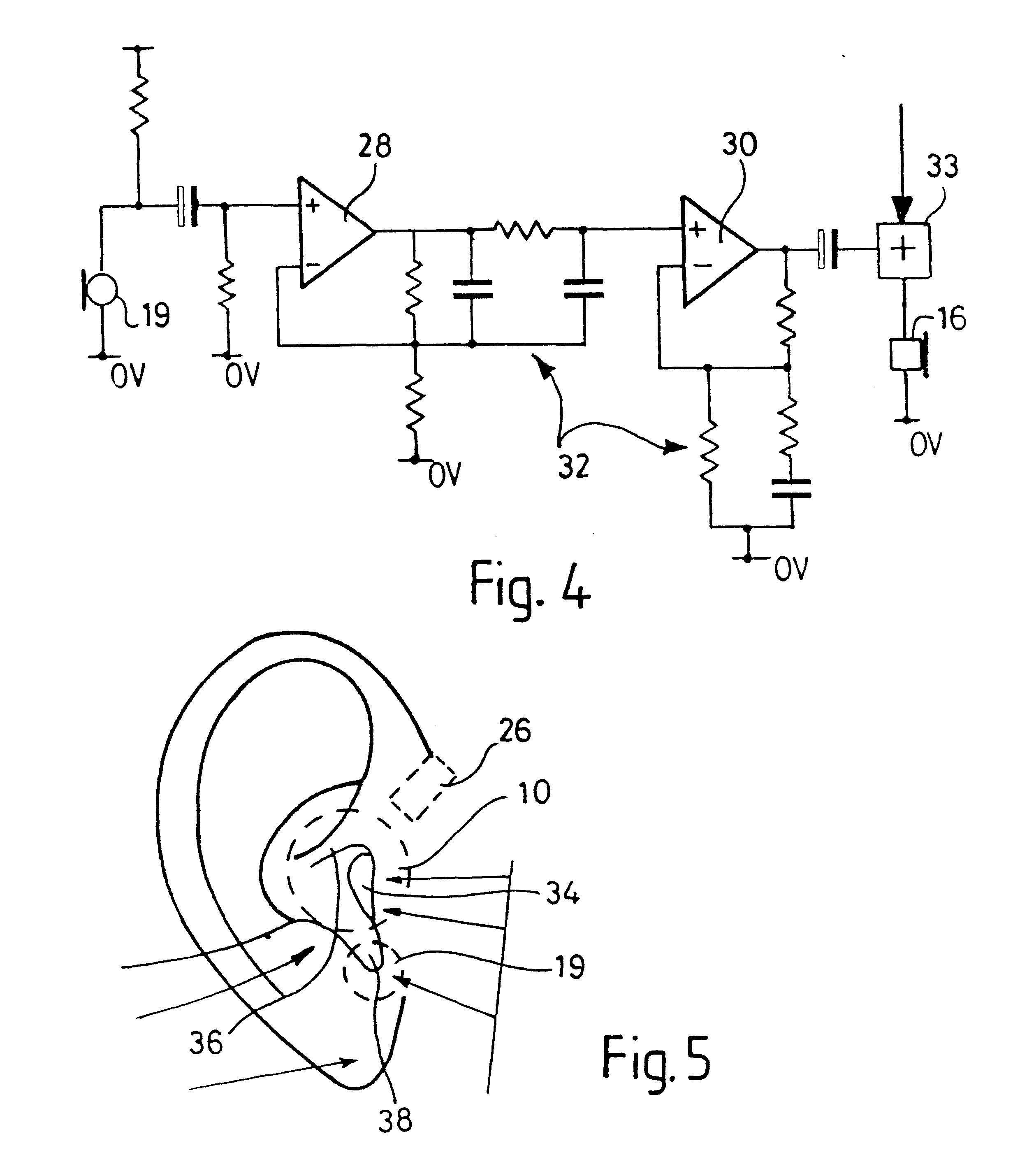
an electronics unit, said electronics unit completing a feedback loop which includes an inverting amplifier means adapted to generate an amplified, phase inverted signal from an unwanted noise signal received from the microphone and to feed said phase inverted signal to the drive unit, the acoustic gain of the loop being increased when the earpiece cushion is compressed against the ear beyond a predetermined extent;
an output circuit for leading the summed signal to the sound generators in the earpieces, thereby effectively to cancel unwanted environmental noise present at the earpieces;
Thus, in accordance with another aspect of the invention, there is provided, for an earpiece adapted to be held against the ear and comprising an earpiece shell, a generally flat baffle plate incorporated in the shell, a sound generator carried by the baffle plate and an earpiece cushion carried by the baffle plate; an earpiece attachment comprising an element having means of attachment to the baffle plate and an upstanding part which, when the attachment is secured to the baffle plate, serves to limit compression of the earpiece cushion.

Problems solved by technology

In various applications, however, passive attenuation is insufficient.
Some environments are simply too noisy for comfort or even safety with only passive earpieces.
In other environments, the elimination of extraneous noise is paramount, and satisfactory results cannot be achieved using passive means.
Although the amplitude of the extraneous noise may be significantly diminished, it is almost impossible to completely isolate the wearer from extraneous noise using passive means.
Cancellation is achieved by propagating anti-noise, identical to the unwanted soundwaves but inverted, which interacts with the unwanted waveform and results in cancellation.
When the anti-noise interacts with the noise within each earpiece, destructive interference between the noise and the anti-noise cancels the unwanted sound.
A problem associated with feedback cancellation systems is that they are prone to instability.
Feedback systems tend to become unstable, for example, if the bandwidth of the system is too broad or the gain of the system is too high.
When instability occurs, the system usually emits a loud noise that is generally unpleasant and occasionally dangerous.
Consequently, the maximum range and effectiveness of feedback systems are limited by parameters designed to keep the feedback system stable.
The acoustic properties of each earpiece, however, affect the characteristics of the anti-noise waveform.
However, these acoustic properties of the headset are not constant under all conditions, and may vary with the force applied to the earpiece onto the user's head.
When high pressure is applied to the earpiece, or when the headset is removed from the user's head, the variation of the earpiece's acoustic properties, particularly the volume and acoustic resistance, may cause instability in the feedback loop.
This instability in turn, causes the control loop to generate unstable oscillations, producing unpleasant and potentially even harmful noise.
Thus, if the volume contained between the user's ear and the earpiece is changed, for example because the user rests the side of the head against a pillow or the like, sound distortion can occur due to a change in frequency response, especially high frequency response.

Method used


Image

  • Headset with ear cushion and means for limiting the compression of the cushion
  • Headset with ear cushion and means for limiting the compression of the cushion
  • Headset with ear cushion and means for limiting the compression of the cushion

Examples


Embodiment Construction

The performance of an active headset is limited by various factors such as the allowed complexity of the electronics, the time delay associated with the acoustics of the drive unit and microphone placement, and the variability of the acoustic environment that occurs between different users. But often dwarfing these factors is the change in the headset transfer function that occurs when the headset is pressed hard against the ear. Depending upon the exact design of the headphone cushion, the acoustic gain can increase by as much as 10-12 dB. If the electronics has been designed to extract the maximum possible cancellation out of the system under normal wearing conditions then this gain increase will cause the active headset to become grossly unstable. The result will be that the headset will squeal with high amplitude at high frequencies and motorboat at low. If this is to be avoided, the loop gain has to be cut down considerably thereby severely curtailing the available cancellation...


PUM


Abstract

An earpiece for a headset, especially a headset incorporating active unwanted noise suppression, wherein the earshell incorporates a baffle plate carrying a sound drive and an ear cushion, whereby the baffle plate also carries an upstanding projection, more especially in the form of a sound transparent dome, which limits the extent to which the cushion can be compressed when the earpiece is pressed inwardly against the ear from its normally fitted condition.

Description

1. Field of the InventionThe present invention relates to headsets, and more particularly but not exclusively to headsets utilizing active noise cancellation.2. Description of the Related ArtConventionally, passive headsets comprise a pair of earpieces coupled by a resilient headband. An annular foam pad attached to each earpiece forms a cushion between the shell of the earpiece and the user's head. The resilient headband presses the earpieces against the user's head. Ambient sound is attenuated before it reaches the wearer's ear by occlusion of sound by the earpieces and absorption of transmitted sound by materials within the earpieces. The degree of attenuation achieved depends upon the nature of the ambient noise and the qualities and characteristics of the individual headset.In various applications, however, passive attenuation is insufficient. Some environments are simply too noisy for comfort or even safety with only passive earpieces. In other environments, the elimination of...

Claims


Application Information

Patent Timeline
IPC IPC(8): G10K11/178G10K11/00H04R1/10H04R5/00H04R5/033
CPCG10K11/1788H04R1/1083G10K2210/1081G10K2210/321G10K2210/3219H04R5/033G10K11/17833G10K11/17821G10K11/17857G10K11/17875
Inventor JONES, OWEN
Owner NCT GROUP
Learn More