Device for anchoring structural cable

a technology for structural cables and devices, applied in cable-stayed bridges, applications, bridges, etc., can solve the problems of significant transverse loading additional bending moments at the anchor block,

Inactive Publication Date: 2004-06-15
FREYSSINET INC
View PDF18 Cites 26 Cited by
  • Summary
  • Abstract
  • Description
  • Claims
  • Application Information

AI Technical Summary

Problems solved by technology

The relatively long distance between the guide and the anchor block (typically more than one meter) is needed to limit excessive angular deflections of each tendon which would carry the risk of damagi...

Method used


Image

  • Device for anchoring structural cable
  • Device for anchoring structural cable
  • Device for anchoring structural cable

Examples


Embodiment Construction

The invention is described hereinbelow in its application to stays, without this implying any limitation.

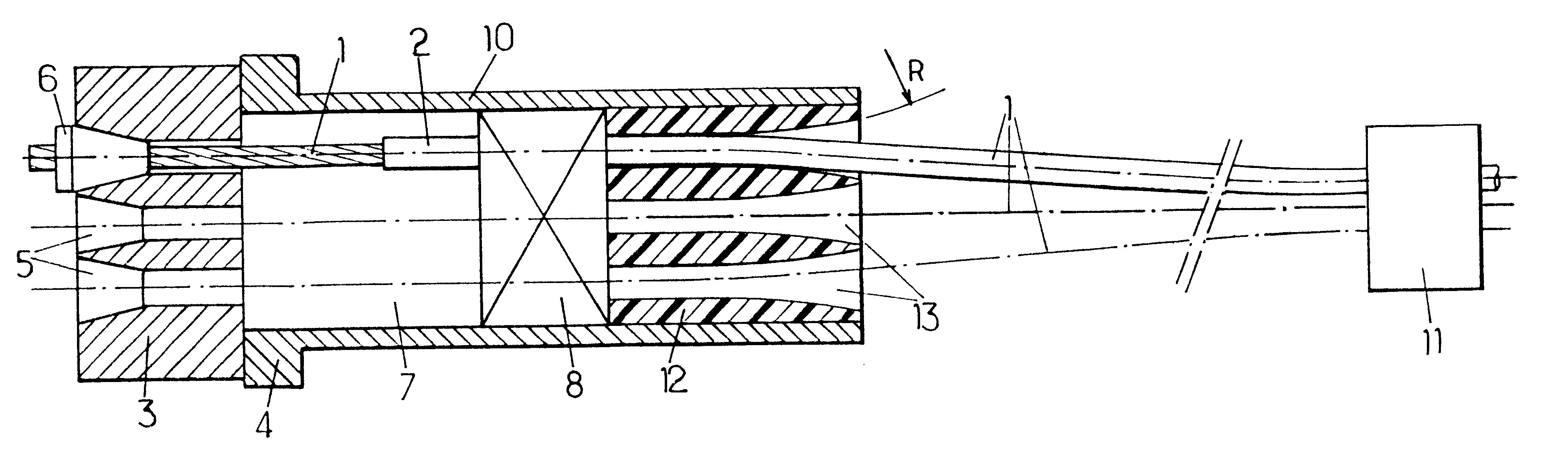
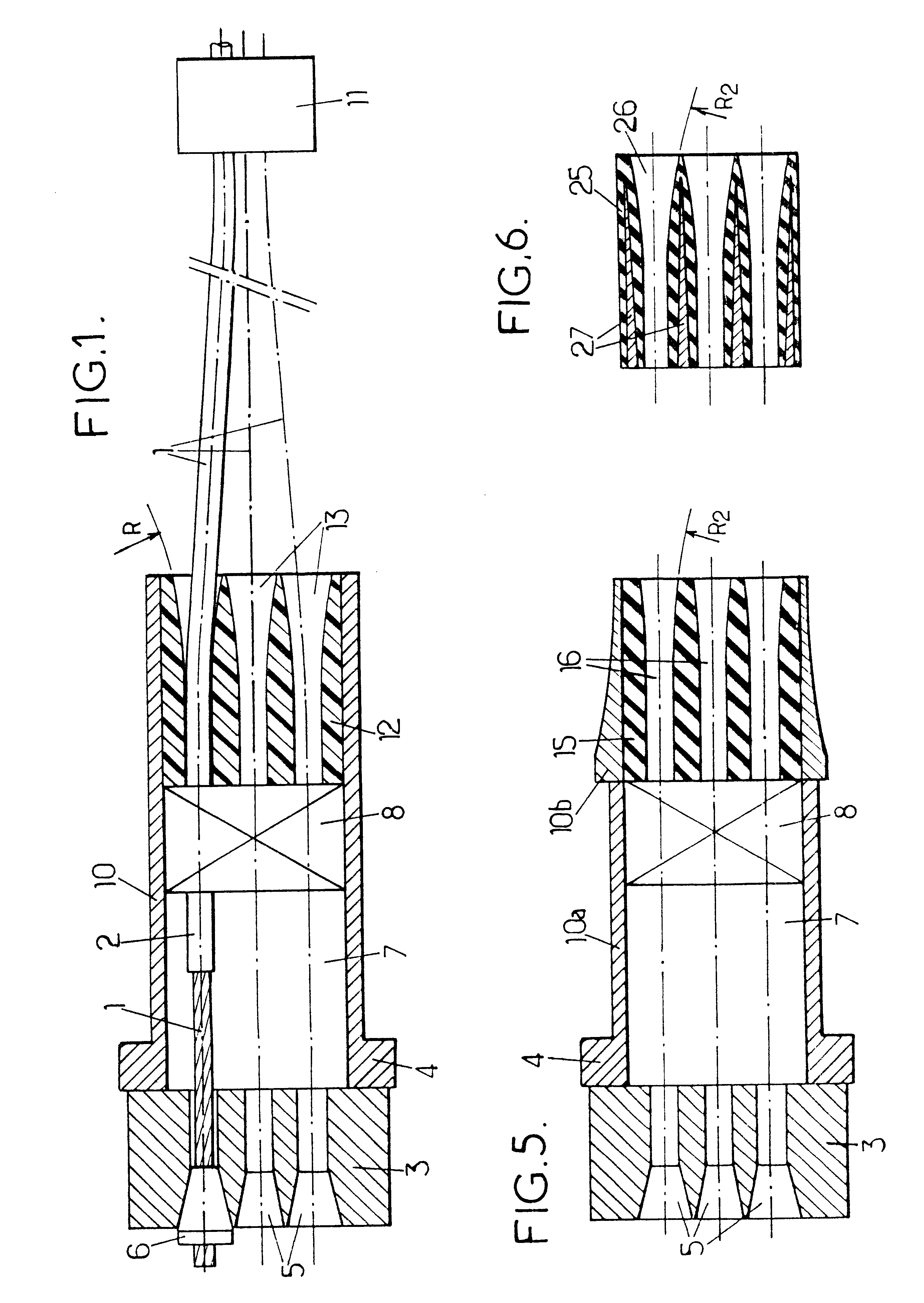
The stay anchored by means of one of the devices described hereinbelow by way of example consists of a bundle of strands 1, just one of which is drawn in FIG. 1. In the example considered here, the strands 1 are of the individually protected type: the assembly of stranded metal wires is coated with a product that affords protection against corrosion (for example a grease) and contained in an individual sheath 2 made of plastic (for example a high density polyethylene (HDPE)).

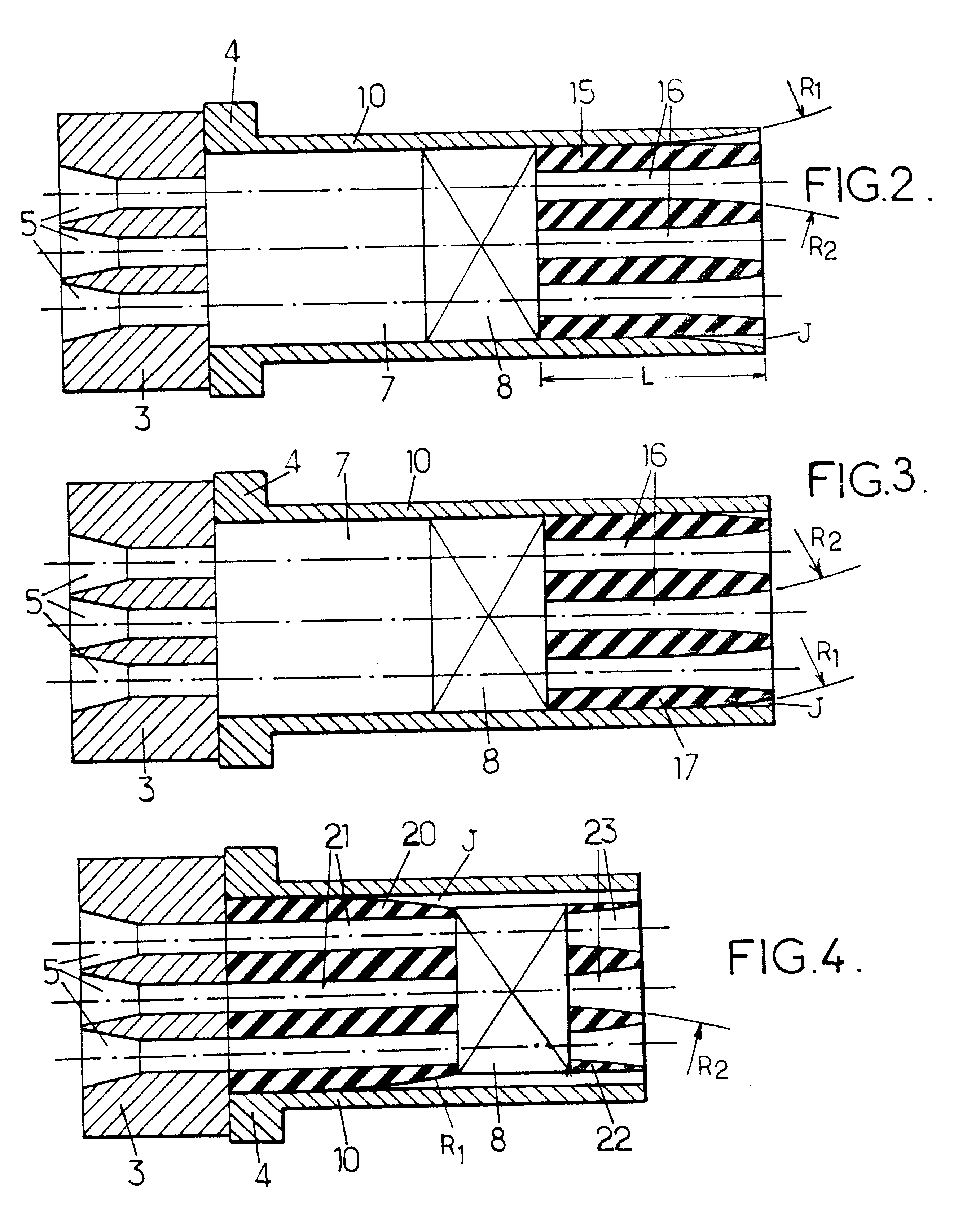
The anchoring device comprises an anchor block 3 applied against a bearing piece 4 along a surface substantially perpendicular to the overall direction of the stay. The bearing piece 4 is pressed, at the opposite end to the anchor block 3, against the structural element to which the stay is connected.

The anchor block 3 has orifices 5 passing through it, which orifices have a frustoconical profile widening tow...


PUM

PropertyMeasurementUnit
Viscosityaaaaaaaaaa
Radiusaaaaaaaaaa
Inertiaaaaaaaaaaa

Abstract

A device having an anchor block having orifices therethrough, each accommodating a tendon of the cable and a means of immobilizing the tendon. The device further includes a bearing piece for the anchor block, and means of guiding the tendons between the anchor block and a running part of the cable. The guide means are connected to the bearing piece and include an individual guide passage for each tendon of the cable, allowing angular deviation thereof. Each guide passages have, in the direction of the anchor block, a transverse layout aligned with that of the orifices in the anchor block.

Description

The present invention relates to the devices used to anchor structural cables used in construction work. It applies in particular to stays, pre-stressing cables and suspension cables of suspension bridges.DESCRIPTION OF THE RELATED ARTThe stays are cables generally designed to transmit tensile loads between two points of a structure to which they are anchored. They are therefore in theory straight, if external effects which tend to curve their path are neglected.The catenary effect due to the self-weight of the stay, the effect of the wind (external transverse pressure), the slight rotational movements of the building elements supporting the stay anchors, the effects of variations in temperature are factors which lead to angular deflections at the ends of the stays, i.e. where they emerge from the anchor points.In other cables, significant deflections as they emerge from the anchor point are also possible because of the line they are forced to follow or because of transverse action ...

Claims


Application Information

Patent Timeline
IPC IPC(8): E01D19/16E01D19/00E04C5/12E01D11/02E01D11/00E01D11/04E01D101/40E04G21/12
CPCE01D19/14E04C5/12E01D19/16Y10T24/3909
Inventor FUZIER, JEAN-PHILIPPESTUBLER, JEROME
Owner FREYSSINET INC
Why Eureka
Try Eureka