
Self-adjusting ring size reducer

a self-adjusting and ring technology, applied in the field of finger ring art and self-sizing rings, can solve the problems of adding unsightly bulk to the ring, too large for the digital portion of the ring finger, and a client with large knuckles

Inactive Publication Date: 2004-06-15
FISCHER RONALD J
View PDF6 Cites 62 Cited by
  • Summary
  • Abstract
  • Description
  • Claims
  • Application Information

AI Technical Summary

Benefits of technology

"The present invention is about improving self-sizing rings for jewelry. The problem that this invention addresses is that when a ring is made or retrofitted to a user, the ring often does not fit perfectly due to changes in the size of the user's fingers. Existing devices that try to solve this problem are often bulky, uncomfortable, or not acceptable in expensive custom jewelry. The invention provides a solution that can be incorporated into new rings during fabrication, making them easier to adjust to changes in finger size. The invention uses a movable cradle or other resilient means to adjust the size of the ring shank and provide a better fit for the user's fingers."

Problems solved by technology

A problem often encountered by jewelers concerns a client who has developed large knuckles due to aging, weight gain, arthritis, etc., compared to the digital portion of the ring finger.
Therefore, when a ring is made or adjusted to fit over the enlarged knuckle, it is too large for the digital portion of the ring finger and will tend to turn on the finger.
A somewhat similar problem confronts jewelers when a ring is passed from one owner to another with the owners having different sized fingers.
These all tend to add unsightly bulk to the ring, are very visible when the ring is worn, are uncomfortable, hard to install or not acceptable when installed in expensive custom made jewelry.
Many of these devices are difficult to produce and even more difficult to retrofit to existing rings.

Method used


Image

  • Self-adjusting ring size reducer
  • Self-adjusting ring size reducer
  • Self-adjusting ring size reducer

Examples


first embodiment

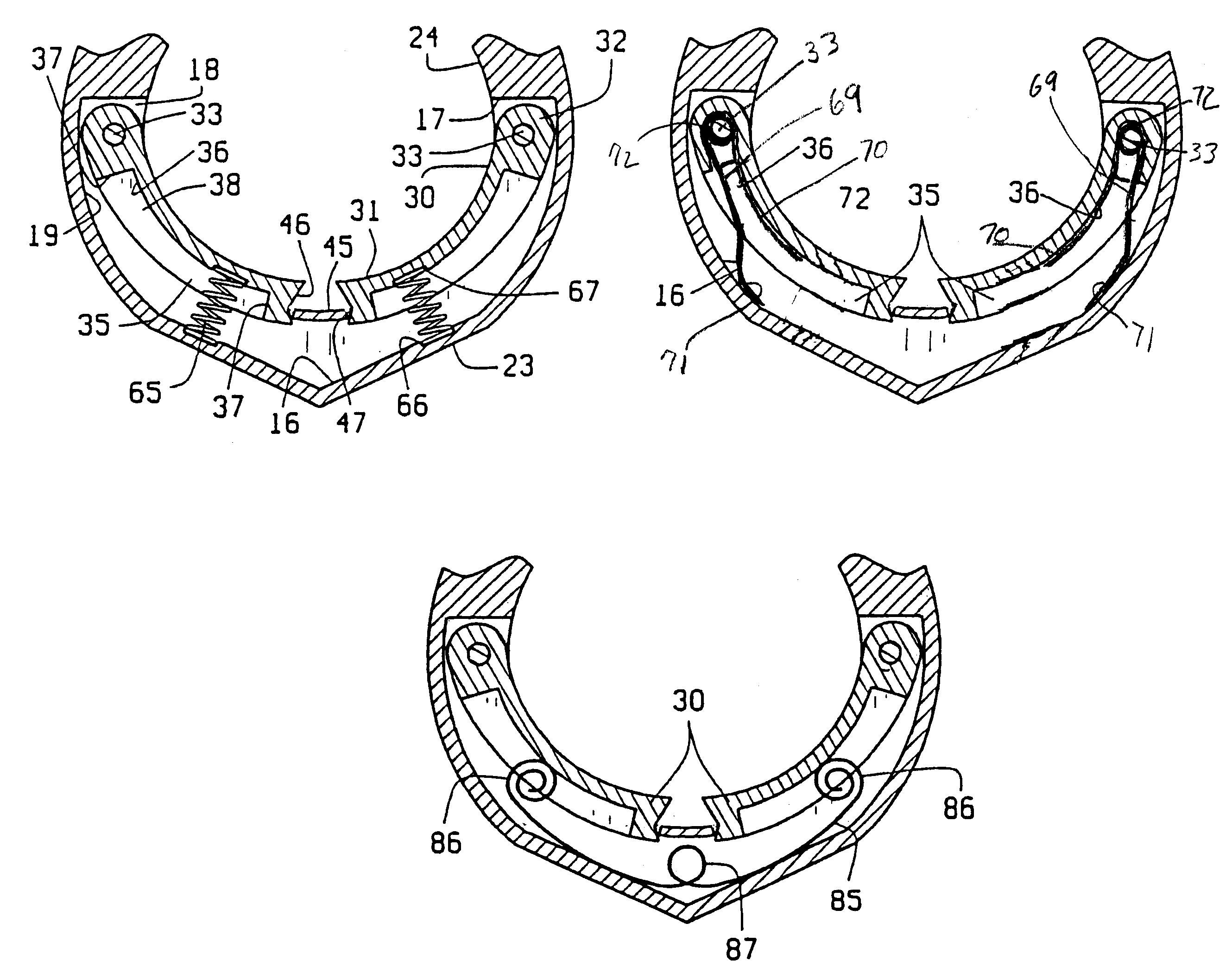
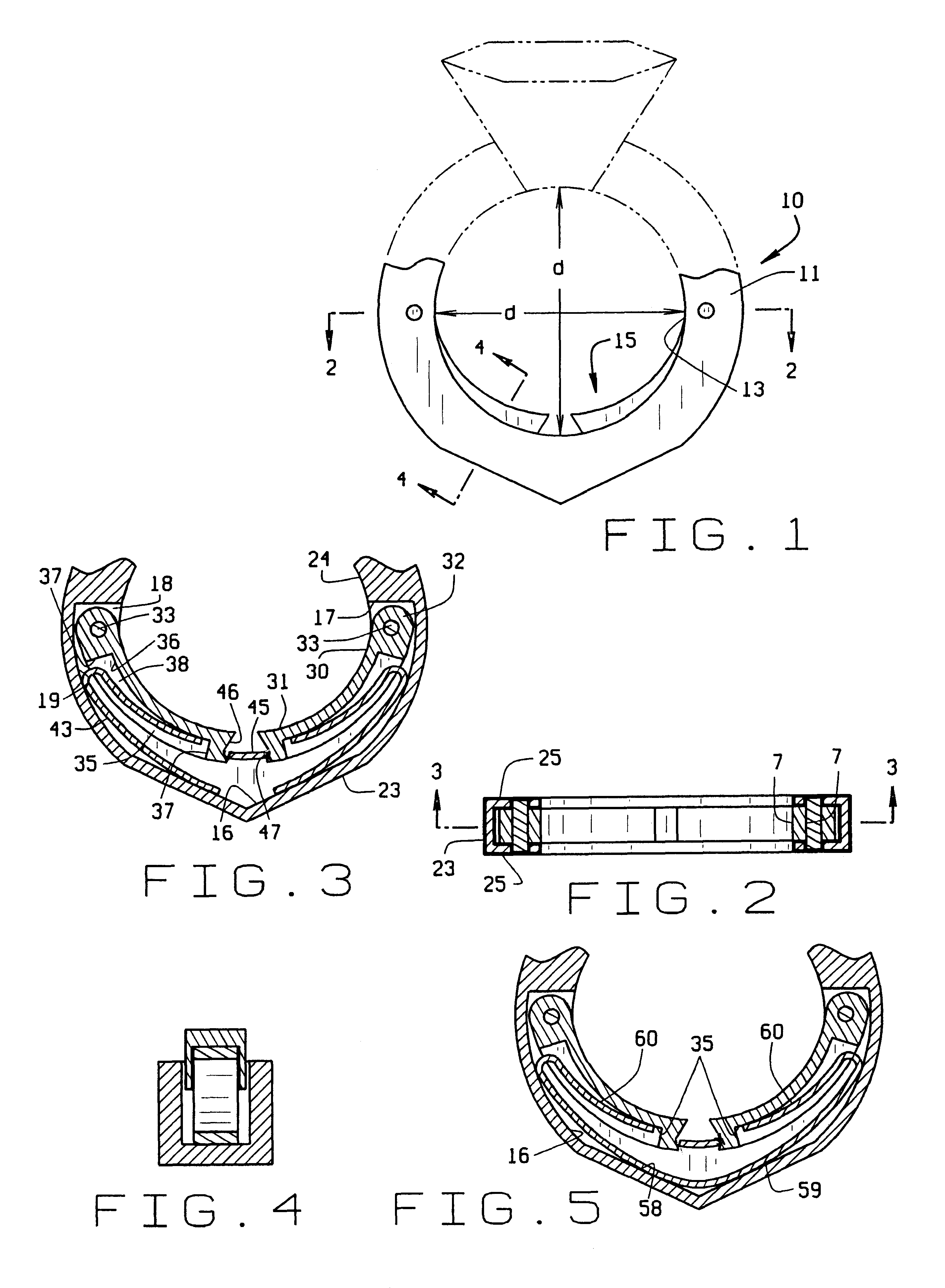
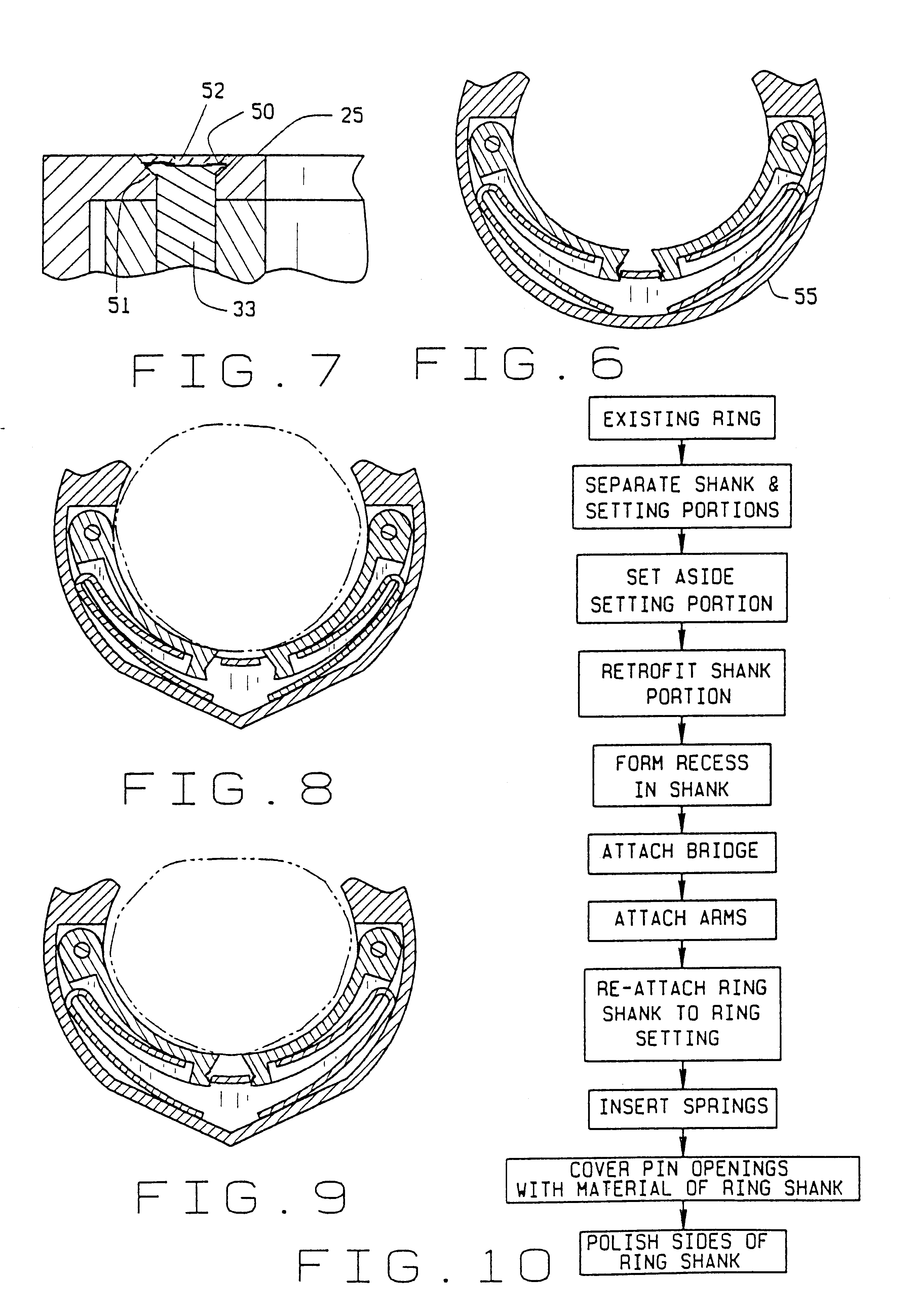
the present invention is shown in FIGS. 1-5 applied to a finger ring is having a shank portion 11 and a setting 12 (shown in broken lines in FIG. 1). The setting 12 forms no part of this invention except that it is not encumbered in any way by the ring shank size adjusting mechanism.

The ring shank 11 defines a finger receiving opening 13 whose nominal size is defined by the distance "d" shown in FIG. 1. Positioned in the lower portion of the shank 11 opposite the setting 12 is a ring shank size reducing mechanism 15. The size reducing mechanism 15 is housed in a recess 16 formed in the lower portion of the ring shank 11. The recess 16 has end walls 17, side walls 18 and a bottom wall 19.

The ring shank 11 itself has an outer edge surface 23, an inner edge surface 24, and outer side surfaces 25.

The ring shank reducing mechanism 15 comprises a pair of opposed arms 30, each having an arcuate finger engaging inner surface 31, and a shoulder 32 pivotally attached in the shank recess 16 ad...


PUM


Abstract

A self-adjusting finger ring size reducing mechanism has spring biased arms pivotally mounted in a slot in the lower shank portion of a ring. The arms are urged into the finger opening by the springs comprised in the slot by the arms and are retained in the slot by a bridge across the top of the slot intermediate its ends which engages the free ends of the arms to limit their movement out of the slot. The mechanism can be retrofitted to existing finger rings.

Description

Not applicable1. Field of the InventionThe present invention is directed to the jewelry art, particularly the finger ring art, and specifically to an improvement in self-sizing rings for reducing the effective size of a ring finger opening to provide a better fit for the user.2. Description of Related ArtA problem often encountered by jewelers concerns a client who has developed large knuckles due to aging, weight gain, arthritis, etc., compared to the digital portion of the ring finger. Therefore, when a ring is made or adjusted to fit over the enlarged knuckle, it is too large for the digital portion of the ring finger and will tend to turn on the finger. This can occur with new rings or with older rings that need to be retrofitted.A somewhat similar problem confronts jewelers when a ring is passed from one owner to another with the owners having different sized fingers. Rings can only be stretched or cut down within small limits without weakening the structure or introducing impe...

Claims


Application Information

Patent Timeline
Patent Type & Authority Patents(United States)
IPC IPC(8): A44C9/02A44C9/00
CPCA44C9/02
Inventor ROEMER, THOMAS BRUCE
Owner FISCHER RONALD J
Learn More