Transflective electrophoretic display

a technology of electrophoretic display and transflective electrode, which is applied in the direction of identification means, instruments, optics, etc., can solve the problems of reducing the efficiency of the backlight system, and the difficulty of achieving high contrast ratio in both bright and dark environments, so as to enhance viewability and improve contrast ratio

Inactive Publication Date: 2004-06-15
E INK CALIFORNIA
View PDF52 Cites 167 Cited by
  • Summary
  • Abstract
  • Description
  • Claims
  • Application Information

AI Technical Summary

Benefits of technology

For applications to be viewed in dark environments, the microcup structure effectively allows the backlight to reach the viewer through the microcup walls. Thus, even a low intensity backlight is sufficient for users to view the transflective EPDs. A photocell sensor to modulate the backlight intensity might also be used to further reduce the power consumption of such EPDs.
The isolated cells are separated by light-transmissive cell walls. The backlight is underneath the bottom electrode plate. The display may also have a background layer above the back light system to control the light passing through the display. The background layer when used is preferably gray. A background layer below the backlight system may also be used to improve the contrast ratio.
A diffuser may also be added onto the top of the transflective display to enhance the viewability.

Problems solved by technology

However, the presence of light scattering particles in the EPD cells greatly reduces the efficiency of the backlight system.
A high contrast ratio in both bright and dark environments is difficult to achieve for traditional EPDs.

Method used


Image

  • Transflective electrophoretic display
  • Transflective electrophoretic display
  • Transflective electrophoretic display

Examples


Embodiment Construction

Definitions

Unless defined otherwise in this specification, all technical terms are used herein according to their conventional definitions as they are commonly used and understood by those of ordinary skill in the art.

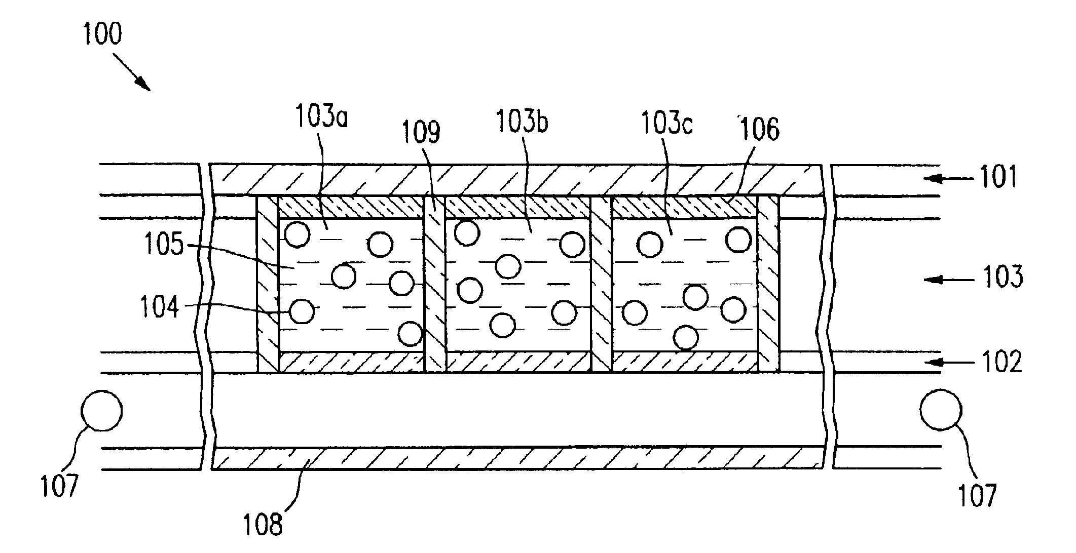
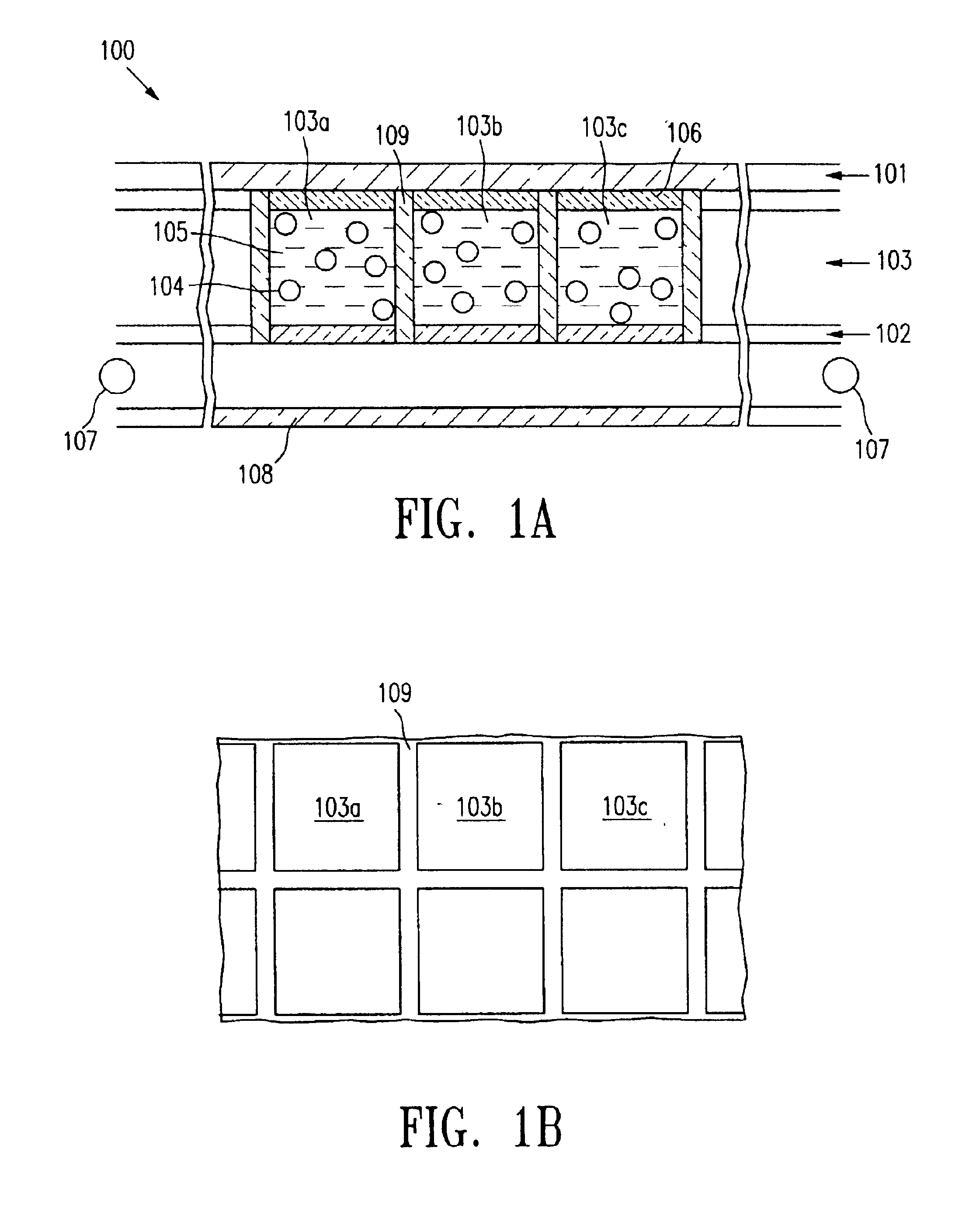
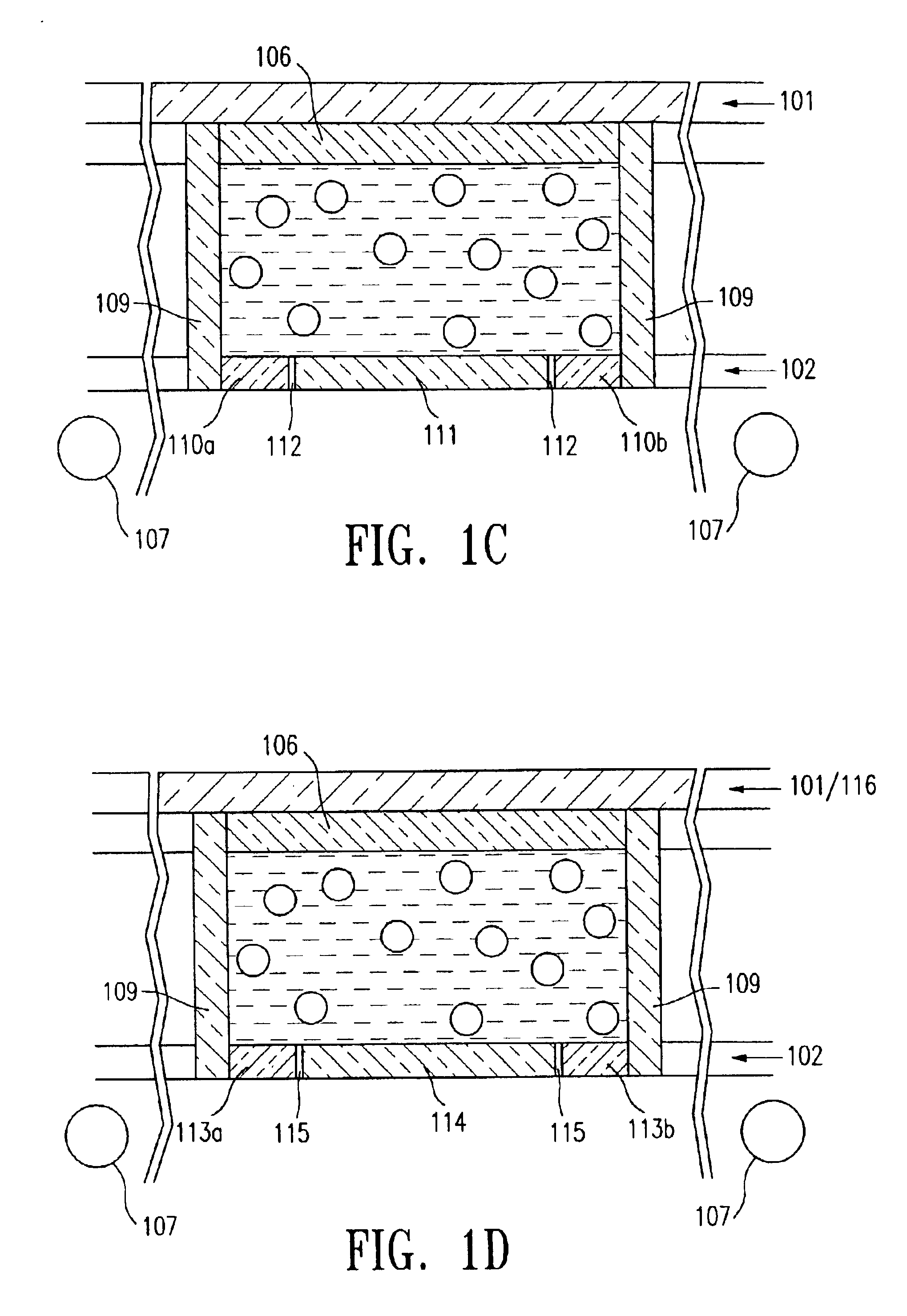
The term "microcup" refers to the cup-like indentations created by microembossing or imagewise exposure.

The term "cell", in the context of the present invention, is intended to mean the single unit formed from a sealed microcup. The cells are filled with charged pigment particles dispersed in a solvent or solvent mixture.

The term "well-defined", when describing the microcups or cells, is intended to indicate that the microcup or cell has a definite shape, size and aspect ratio which are pre-determined according to the specific parameters of the manufacturing process.

The term "aspect ratio" is a commonly known term in the art of electrophoretic displays. In this application, it refers to the depth to width or depth to length ratio of the microcups.

The term "isolated" re...


PUM

PropertyMeasurementUnit
depthaaaaaaaaaa
depthaaaaaaaaaa
mean particle sizeaaaaaaaaaa

Abstract

This invention relates to an electrophoretic display comprising isolated cells of well-defined shape, size and aspect ratio which cells are filled with charged pigment particles dispersed in a solvent, a backlight and optionally a background layer. The display may have the traditional up / down switching mode, an in-plane switching mode or a dual switching mode.

Description

BACKGROUND OF THE INVENTION1. Field of the InventionThis invention relates to a transflective electrophoretic display comprising isolated cells of well-defined shape, size and aspect ratio. The cells are filled with charged particles dispersed in a dielectric solvent and the display has a backlight.The display may have the traditional up / down switching mode, the in-plane switching mode or the dual switching mode.2. Description Of Related ArtThe electrophoretic display (EPD) is a non-emissive device based on the electrophoresis phenomenon influencing charged pigment particles suspended in a colored dielectric solvent. This general type of display was first proposed in 1969. An EPD typically comprises a pair of opposed, spaced-apart plate-like electrodes, with spacers predetermining a certain distance between the electrodes. At least one of the electrodes, typically on the viewing side, is transparent. For the passive type of EPDs, row and column electrodes on the top (the viewing sid...

Claims


Application Information

Patent Timeline
Patent Type & Authority Patents(United States)
IPC IPC(8): G02F1/01G02F1/167G02F1/1343G02F1/1679G09F9/37
CPCG02F1/167G02F1/134363G02F2001/1672G02F2201/12G02F2203/09G02F1/1681G02F1/1679
Inventor LIANG, RONG-CHANGCHEN, DAVIDCHUNG, JERRY
Owner E INK CALIFORNIA
Why Eureka
Try Eureka