Coating transfer device

a transfer device and coating technology, applied in the direction of erasing devices, other chemical processes, paper hanging, etc., can solve the problems of high cost, easy spoiled coating, and easy loss of removable caps,

Inactive Publication Date: 2004-07-13
TOMBOW PENCIL CO LTD
View PDF3 Cites 25 Cited by
  • Summary
  • Abstract
  • Description
  • Claims
  • Application Information

AI Technical Summary

Benefits of technology

It is an object of the present invention to provide an improved coating transfer device having a cover for protecting a coating on a transfer tape when the device is not in use. It is a further object of the invention to provide a coating transfer device having a cover which can be manufactured at reasonable cost. It is still another object of the invention to provide a coating transfer device having a cover without relying upon any cap that can get lost during use of the device, or any rotatable or like means that can easily break.
There is no fear of the cover being easily lost, since it is held by the casing when the device is used, while its front end portion protrudes to protect the coating on the unused portion of the transfer tape when the device is not used. There is no fear of the cover failing easily, either, since no rotary or like mechanism that is easily broken is used to attach the cover to the casing. The absence of any such mechanism also makes the device less expensive to manufacture. Moreover, the cover is reliably held in position both when the device is used, and when it is not used. There is no fear of the cover sliding inadvertently and hindering the use of the device, while it protects the coating on the transfer tape completely when the device is not used.
According to a preferred embodiment of the invention the engaging portion comprises a projection engaging with each guide member to cause the front end portion of the cover to be elastically curved away from the transfer tape to maintain an appropriate distance between the inner surface of the front end portion of the cover and the tape. This arrangement ensures that the inner surface of the front end portion of the cover does not contact and damage the coating on the transfer tape.
According to another embodiment of the invention the cover has a width which is larger than the distance between the guide members and the engaging member has a transversely extending length which is larger than the distance between the guide members. The cover extends over the whole distance between the two guide members and is still more effectively held in its position in which the device is not used, thereby ensuring the still more effective protection of the coating on the transfer tape.
According to a further embodiment of the invention the supporting portion is formed on the bottom of the casing which faces the inner surface of the cover. Thereby cover is still more effectively held in its position in which the device is used.
Finally according to a further embodiment of the invention each guide member has on its bottom edge a projection which is engageable with the engaging portion of the cover. The cover has its front end portion curved away from the transfer tape still more easily and thereby ensures the still more effective protection of the coating on the tape.

Problems solved by technology

The coating, however, is easily spoiled as it is exposed on the outer surface of the transfer tape even when the device is not in use.
In the former case, however, the removable cap is not only likely to get lost easily during the use of the device, but is also costly as it is made to cover the whole transfer head.
In the latter case, the cap is not only likely to break easily at its portion supported rotatably on the casing, but also calls for a complicated and costly mold for making a mechanism for supporting it rotatably.

Method used


Image

  • Coating transfer device
  • Coating transfer device
  • Coating transfer device

Examples


Embodiment Construction

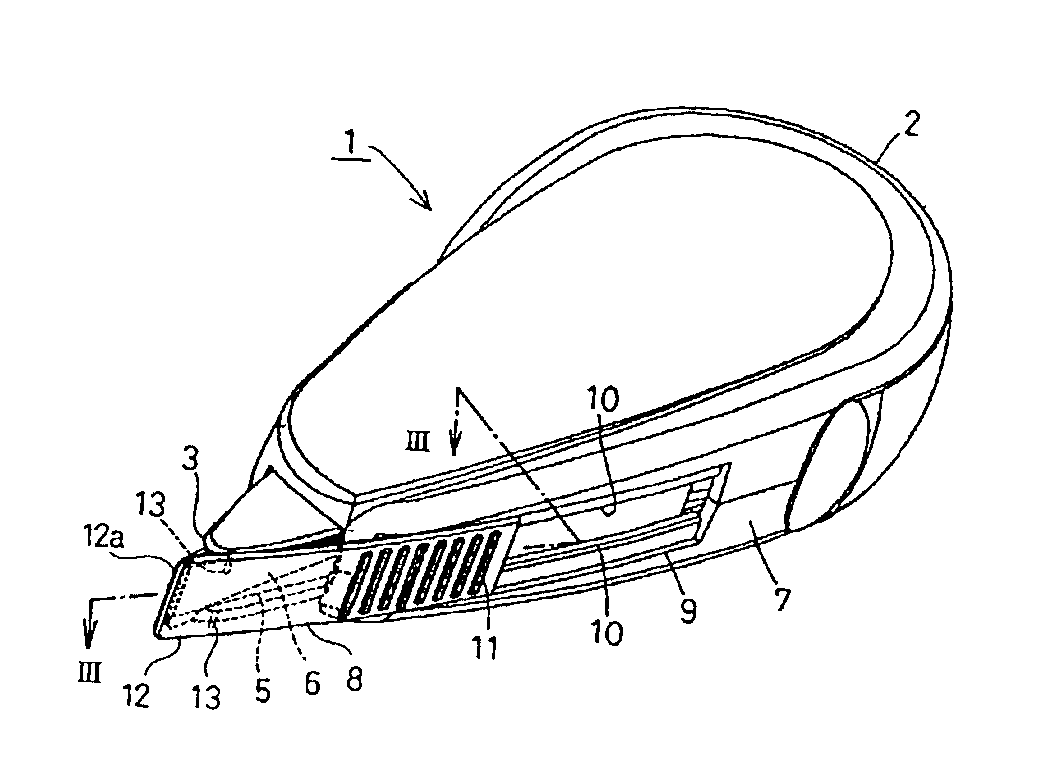
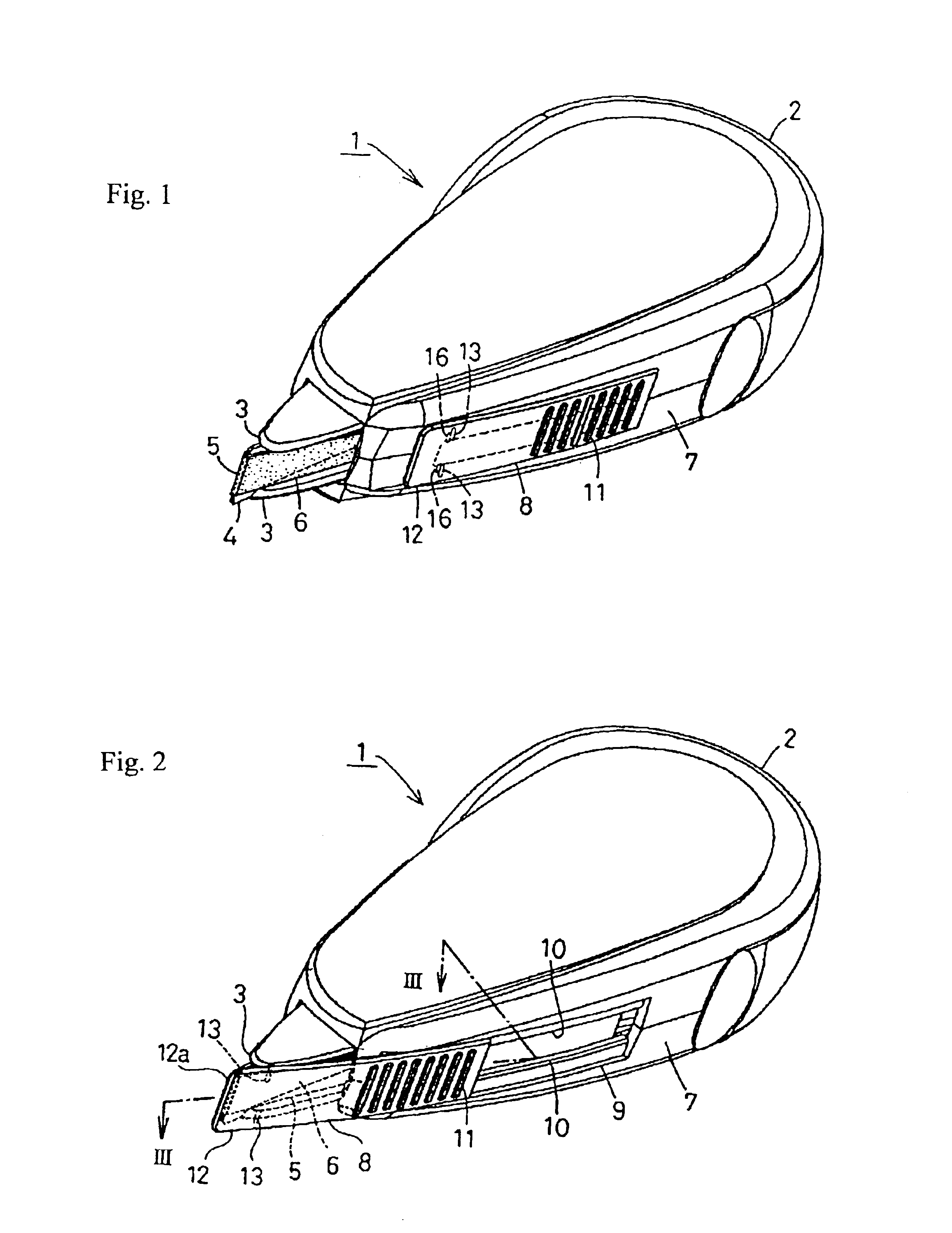
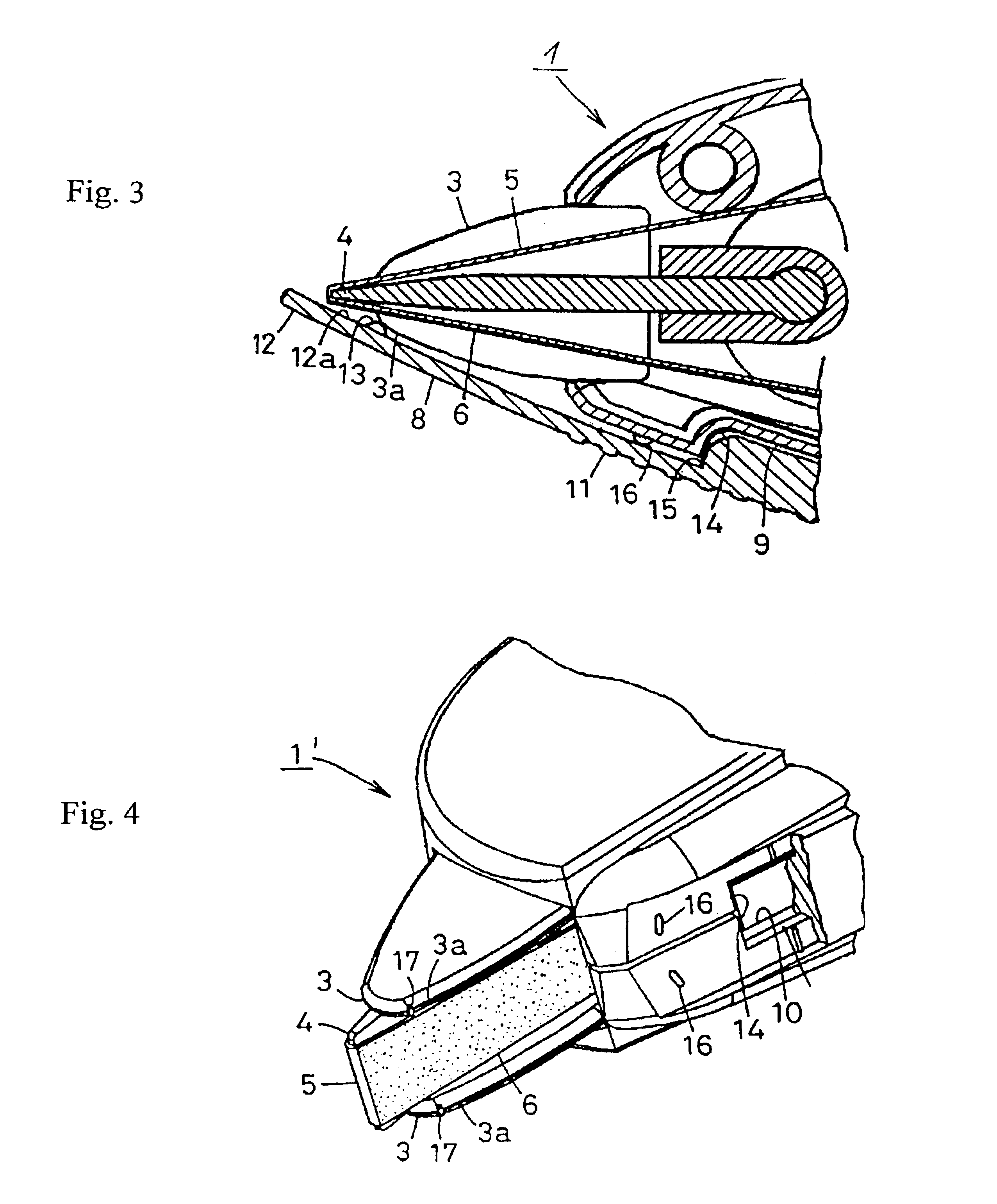
Referring first to FIGS. 1 to 3, a coating transfer device 1 according to one embodiment of the invention has a casing 2 and a transfer head 4 protruding from the front end of the casing 2 and having a pair of transversely spaced apart guide members 3. A transfer tape 5 extends around the transfer head 4 and carries a film-like coating 6, e.g. made of a correcting material, or paste, on its outer surface. When the device 1 is used, it is held upright so that its rightside bottom portion as viewed in FIG. 1 may face downward, the transfer head 4 is pressed at its front edge against a paper or like substrate surface, and the device 1 is drawn thereby the transfer tape 5 may slide clockwise past the front edge of the transfer head 4 to transfer the coating 6 onto the paper or like surface.

According to a salient feature of this invention, the device 1 includes a protective cover 8 formed from an elongated sheet material and attached longitudinally slidably to a bottom portion 7 of the c...


PUM

PropertyMeasurementUnit
distanceaaaaaaaaaa
lengthaaaaaaaaaa
widthaaaaaaaaaa

Abstract

A device for transferring a coating onto a paper or like surface from the outer surface of a transfer tape extending around a transfer head protruding from a casing and having a pair of transversely spaced apart guide members. A protective cover is held within the casing when the device is used and has a front end portion adapted to protrude from the casing for protecting the coating on the unused portion of the transfer tape when the device is out of use. The cover has an engaging portion formed on the inner surface of its front end portion for engaging with the bottom edges of the guide member at its front end to hold the cover in its position in which the device is out of use, while the engaging portion is engageable with a supporting portion formed on the casing to hold the cover in its position in which the device is in use.

Description

FIELD AND BACKGROUND OF THE INVENTIONThis invention relates to a coating transfer device, and more particularly, to an improved coating transfer device having a cover for protecting a coating on a transfer tape when it is out of use.There is known a coating transfer device used for transferring a coating, such as a layer of a correcting material, or paste, onto e.g. a paper surface from the outer surface of a transfer tape extending around a transfer head protruding from a casing. The coating, however, is easily spoiled as it is exposed on the outer surface of the transfer tape even when the device is not in use. It is, therefore, usual to employ a removable cap for covering the whole transfer head including the transfer tape, or a cap supported rotatably at one end on the casing for covering that portion of the transfer head along which the unused transfer tape portion extends. In the former case, however, the removable cap is not only likely to get lost easily during the use of th...

Claims


Application Information

Patent Timeline
Patent Type & Authority Patents(United States)
IPC IPC(8): B65H37/00B43M11/06B43L19/00C09K3/00
CPCB65H37/007Y10T156/1795Y10T156/18B43L19/00
Inventor SHINYA, MASASHI
Owner TOMBOW PENCIL CO LTD
Why Eureka
Try Eureka