Projection system

a projection system and projection technology, applied in the field of projection systems, can solve the problems of reducing brightness, affecting the image contrast, and affecting the image quality,

Inactive Publication Date: 2004-07-13
ARSENICH SVYATOSLAV IVANOVICH
View PDF11 Cites 21 Cited by
  • Summary
  • Abstract
  • Description
  • Claims
  • Application Information

AI Technical Summary

Benefits of technology

The object of the invention is to provide inexpensive small-dimension and lower-weight projection systems having reflecting or translucent viewing screens to project mono- and stereoscopic quality images in any scales of magnification of an image in a bright external parasitic illumination of the screen image.

Problems solved by technology

The major disadvantage of the above-discussed projection systems is their large dimensions and considerable weight.
This disadvantage is connected with the necessity to carry out projection in a large projection space between a projector and viewing screen at a projection distance that must be not less than the length of the screen image diagonal.
The technical paradox is that a reflecting or translucent viewing screen in case of projection of a bright and sharp image must reflect or, respectively, transmit the projected light flux to the maximal extent.
Thereupon in viewing the screen images when a viewing screen has an external parasitic illumination, the image contrast deteriorates significantly, brightness is lowered at the edges of the screen image field, and the colour-rendering accuracy is lost.
In this case, a lower quality of the screen images restrains possibilities to use projection systems in illuminated premises and outdoors.
This difficulty is connected with design problems of the modern projection systems that permit the projection within the projection angles (angle of the axis inclination with respect to the viewing screen perpendicular) of not over 30.degree..
A disadvantage of the rear- and front projection systems is the necessity of a large volume of the projection space, without shadowing by external objects.
Further, the lenticular-raster screens are known to reduce significantly the brightness and colour-rendering accuracy from the centre to edges of the screen image, particularly when in viewing at the aspects near to the edge of the viewers' location sector.
Besides, an excessive growth of dimensions and weight of the prior-art rear projection systems is caused by the necessity to place a projection system in a light-protected premises or a housing containing projection mirrors, and the need to have means for rigid suspension of a projector.
These problems, and also the need for a longer projection distance between a projector and screen (comparable with the image diagonal length) complicate design of the prior-art rear- and front projection systems and make them more expensive.

Method used


Image

  • Projection system
  • Projection system

Examples


first embodiment

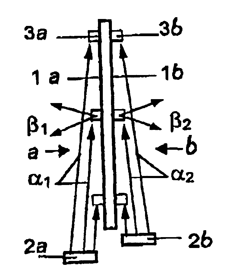
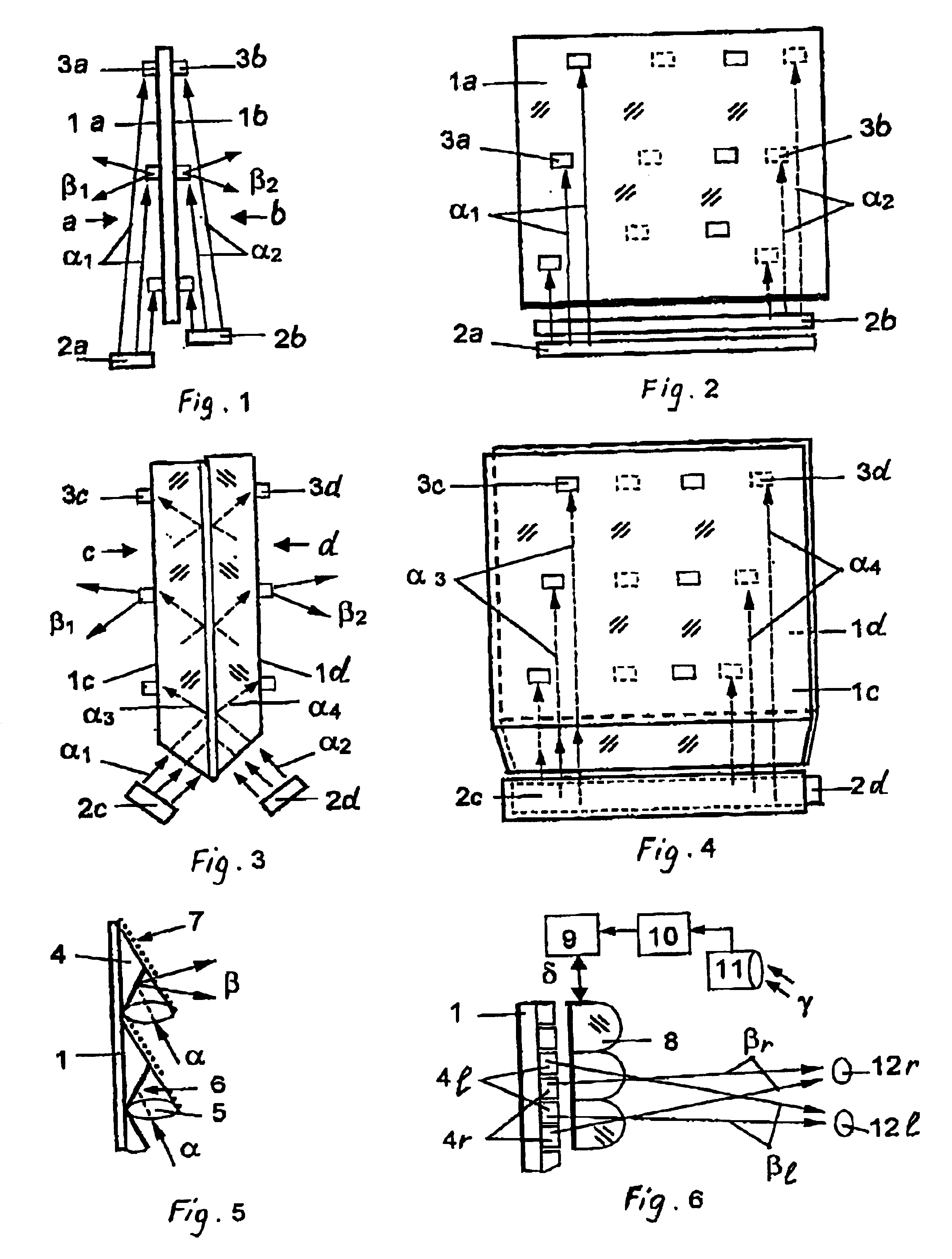
In the claimed projection system as shown in FIGS. 1 and 2: viewing screen 1 is designed as a flat thin plate; in the lower end-face of the screen, projectors 2a and 2b are positioned. On both sides of the screen, the area of observation of the screen images is provided with light diffusers 3a (on the front side a of the screen), and light diffusers 3b on the front side b of the screen. The light diffusers are intended to capture the projection rays .alpha..sub.1 and .alpha..sub.3 (directed from the screen end-face) and for subsequent deflection and diffusing of the rays, respectively, in angle .beta..sub.1 of the screen image observation sector from side a of the screen, and in angle .beta..sub.2 of observation sector of another screen image from side c of the screen. Screen surfaces 1a and 1b around the light diffusers are coated with an anti-flare black opaque layer, or are transparent or coated with a photochrome film (to adjust transparency by the external ultraviolet illuminat...

second embodiment

In FIGS. 3 and 4 the claimed projection system having a viewing screen consisting of two flat-parallel light guides is operated as follows.

Below, from the end-face side of screen 1c and 1d, projectors 2c and 2d form the projected light fluxes of images in the form of narrowly diverging rays .alpha..sub.3 and, correspondingly, .alpha..sub.4. Projector 2c, from below through the end-face of light guide 1c projects rays .alpha..sub.3. These rays are reflected inside the light guide in the form of rays .alpha..sub.3 that diverge to points of certain light diffusers 3c, then they are outputted, deflected and diffused by said light diffusers in broad angle .beta..sub.1 of the screen image observation sector from side c. Similarly, projector 2d forms the screen images to be viewed from the opposite side d of the screen.

FIG. 5(a) shows projection screen 1 having light diffusers 4 in the form of lenses 5 provided with flat inclined mirrors 6 and opaque black coating 7. Light diffusers are in...


PUM


Abstract

The present invention relates to projection systems for displaying visual information in a variety of applications in order to reduce the projection area, the weight and the dimensions thereof. In one embodiment, the projection system for producing an external surface projection on a visualization screen comprises a flat and thin visualization screen for carrying out projection on both sides. Images can be watched on the left side and on the right side of this screen. From the surface of the screen and on the left and right sides thereof, projectors are provided for projecting images simultaneously on both sides of the screen. Light diffusers are provided on both sides of the screen. The projections are converted through the optics of the projectors so as to form reduced-divergence projection beams which are entirely captured by the light diffusers and which are diverted and diffused at wide angles of image observation ranges.

Description

The invention relates to projection systems to project mono- and stereoscopic images on a large viewing screen by the optical projection technique.The proposed projection systems are intended for the consumer-oriented and professional applications in cine-, tele-, video- and computer-projection, projection of theatrical scenery, advertisements, as well as for other purposes. For generating the projected images, the presently-used and proposed updated episcopes, diascopes, cine-projectors, and video, tele-and computer projectors can be used. The proposed reflecting or translucent viewing screens are capable of providing high optical parameters of the screen images and considerable operation capabilities of projection not known in the prior art.PRIOR ARTThe extensively-used and available projection systems comprise a projector and a projection screen. The front-projection systems serve to project images onto a reflecting (front-projection) screen or a white wall, and the rear-projecti...

Claims


Application Information

Patent Timeline
Patent Type & Authority Patents(United States)
IPC IPC(8): F21V8/00G02B27/02H04N13/00G02B6/00G02B3/00G02B5/00G02B5/04G02B5/08G03B21/60G03B35/20G09F19/18H04N13/04
CPCG02B6/0018G02B6/0043G02B27/02H04N13/0404H04N13/0468H04N13/0497G02B6/0076G09F19/18H04N13/305H04N13/366H04N13/398
Inventor ARSENICH, SVYATOSLAV IVANOVICH
Owner ARSENICH SVYATOSLAV IVANOVICH
Why Eureka
Try Eureka