Control system of electric motor
a control system and electric motor technology, applied in the direction of electric generator control, dynamo-electric converter control, dynamo-electric gear control, etc., can solve the problems of lowering prone to failure, and prone to failure, so as to reduce the working efficiency of the motor, the fluctuation of the battery voltage can be easily tracked or controlled, and the control accuracy is low.
- Summary
- Abstract
- Description
- Claims
- Application Information
AI Technical Summary
Benefits of technology
Problems solved by technology
Method used
Image
Examples
first embodiment
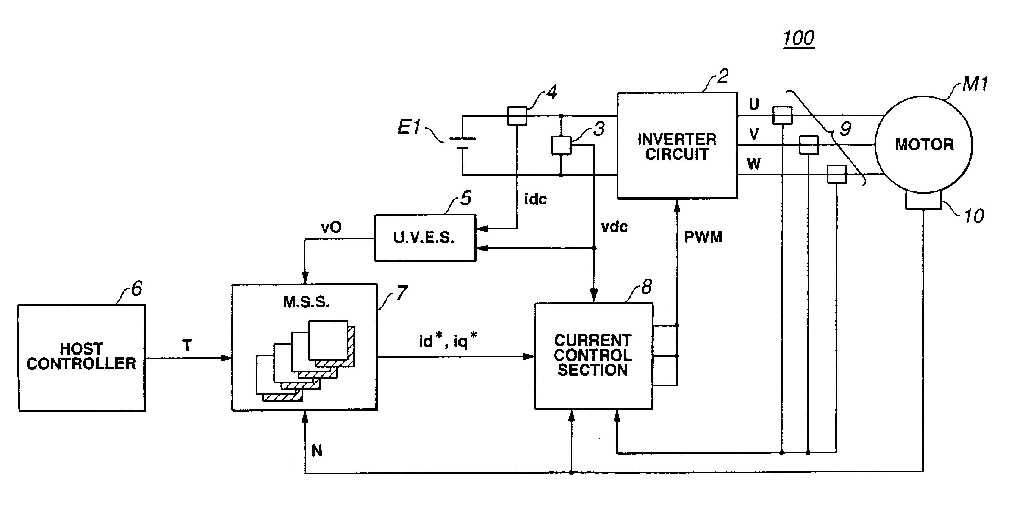
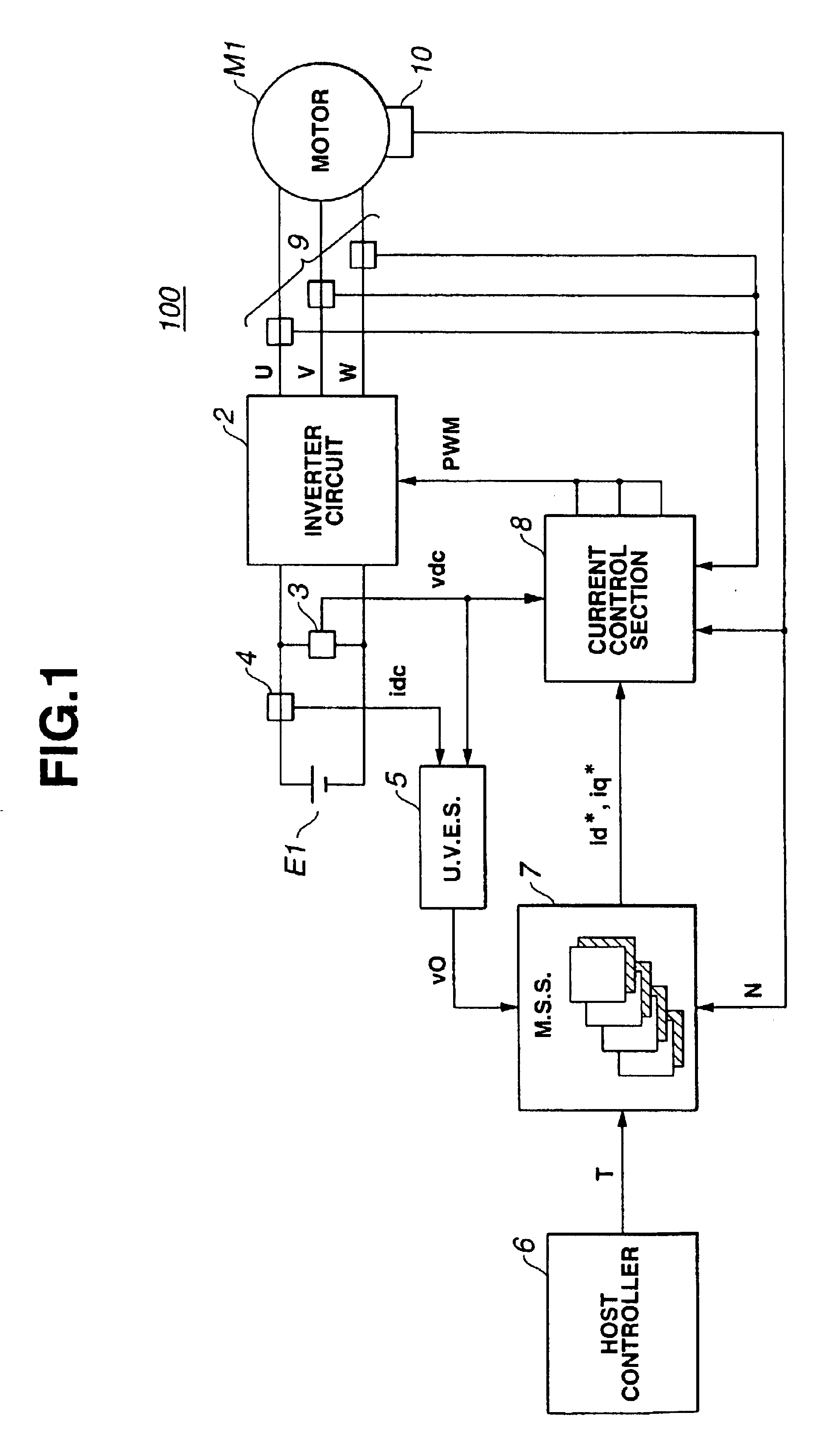
Referring to FIG. 1, there is schematically shown a control system 100 of an electric motor "M1", which is the present invention.
The motor "M1" is of a synchronous type. That is, the control system 100 is arranged to control operation of the synchronous motor "M1".
The control system 100 comprises an inverter circuit 2 that inverts or converts a direct current from a battery "E1" to a three-phase alternating current which is fed to synchronous motor "M1", a voltmeter 3 that detects a magnitude "vdc" of an output voltage of battery "E1", and an ammeter 4 that detects a magnitude "idc" of output current from battery "E1".
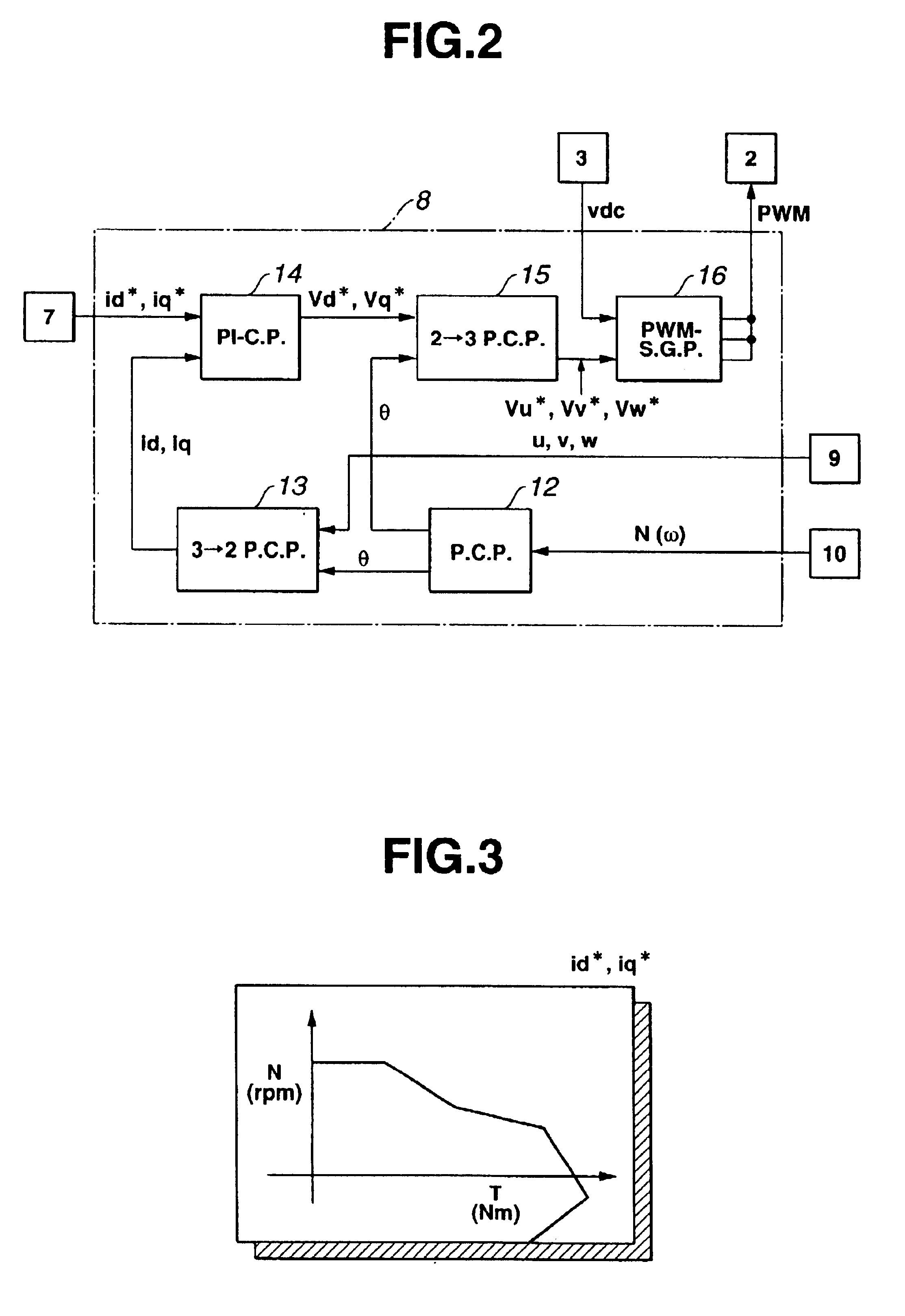
Furthermore, the control system 100 comprises an unloaded voltage estimation section (or U. V. E. S) 5 that, based on the detected voltage "vdc" from voltmeter 3 and the detected current "idc" from ammeter 4, estimates an output voltage "v0" that would be outputted from battery "E1" when battery is unloaded, a current sensor 9 that detects a magnitude of current flowin...
second embodiment
Referring to FIG. 4, there is shown schematically a control system 200 of an electric motor "M1", which is the present invention.
Since the second embodiment 200 is similar to the above-mentioned first embodiment 100, only portions or parts which are different from those of the first embodiment 100 will be described in detail in the following.
As shown, in the second embodiment 200, there is employed a current command setting section 22 which includes an unloaded voltage estimation part (or U. V. E. P.) 22a and a map storing part (or M. S. P.) 22b. However, in the second embodiment 200, there is no means corresponding to ammeter 4 employed in the first embodiment 100.
FIG. 5 shows schematically current command maps installed or memorized in map storing part 22b of current command setting section 22. As shown, each map indicates d-axis current command "id*", q-axis current command "iq*" and direct current voltage "vdc'" with respect to torque command "T" (Nm) outputted from host control...
PUM
 Abstract
Description
Claims
Application Information
 - R&D
- Intellectual Property
- Life Sciences
- Materials
- Tech Scout
- Unparalleled Data Quality
- Higher Quality Content
- 60% Fewer Hallucinations
Browse by: Latest US Patents, China's latest patents, Technical Efficacy Thesaurus, Application Domain, Technology Topic, Popular Technical Reports.
© 2025 PatSnap. All rights reserved.Legal|Privacy policy|Modern Slavery Act Transparency Statement|Sitemap|About US| Contact US: help@patsnap.com


