Line narrowing of molecular fluorine laser emission

Inactive Publication Date: 2004-07-13
LAMBDA PHYSIK
View PDF25 Cites 1 Cited by
  • Summary
  • Abstract
  • Description
  • Claims
  • Application Information

AI Technical Summary

Problems solved by technology

Commonly the bandwidth of the natural emission of the DUV or VUV laser being used is too broad to be used with projection illumination systems.
All of thes

Method used


Image

  • Line narrowing of molecular fluorine laser emission
  • Line narrowing of molecular fluorine laser emission
  • Line narrowing of molecular fluorine laser emission

Examples


Embodiment Construction

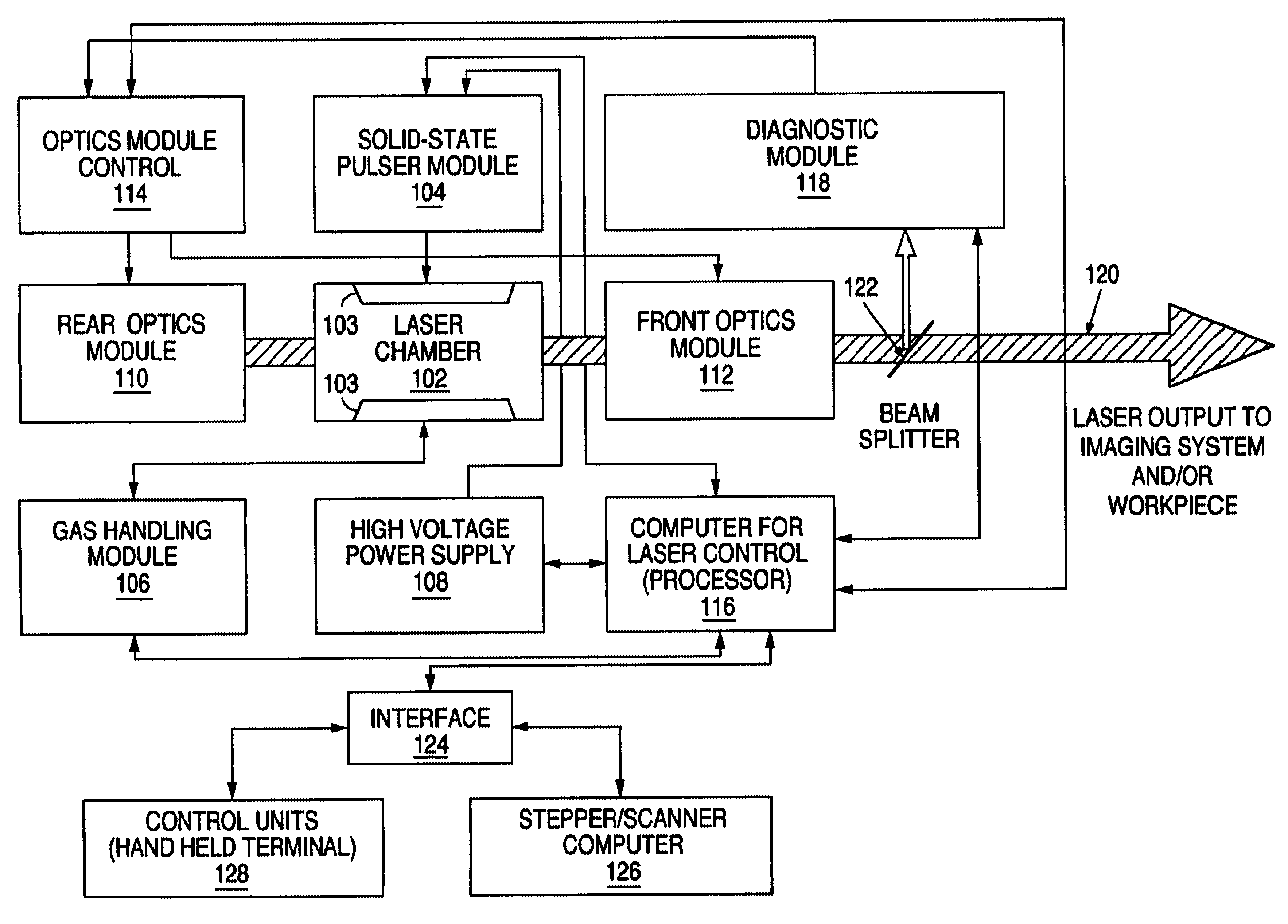
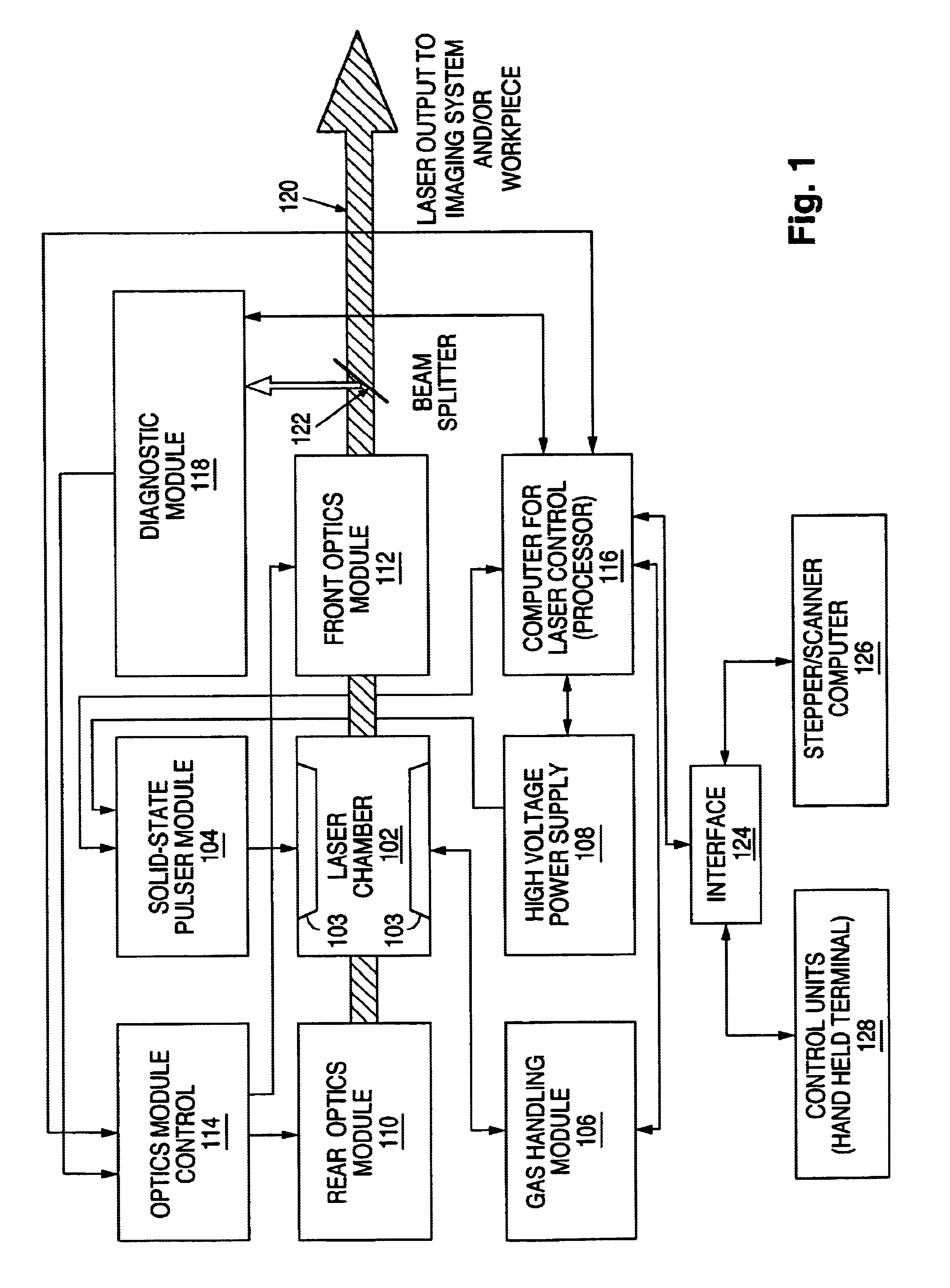
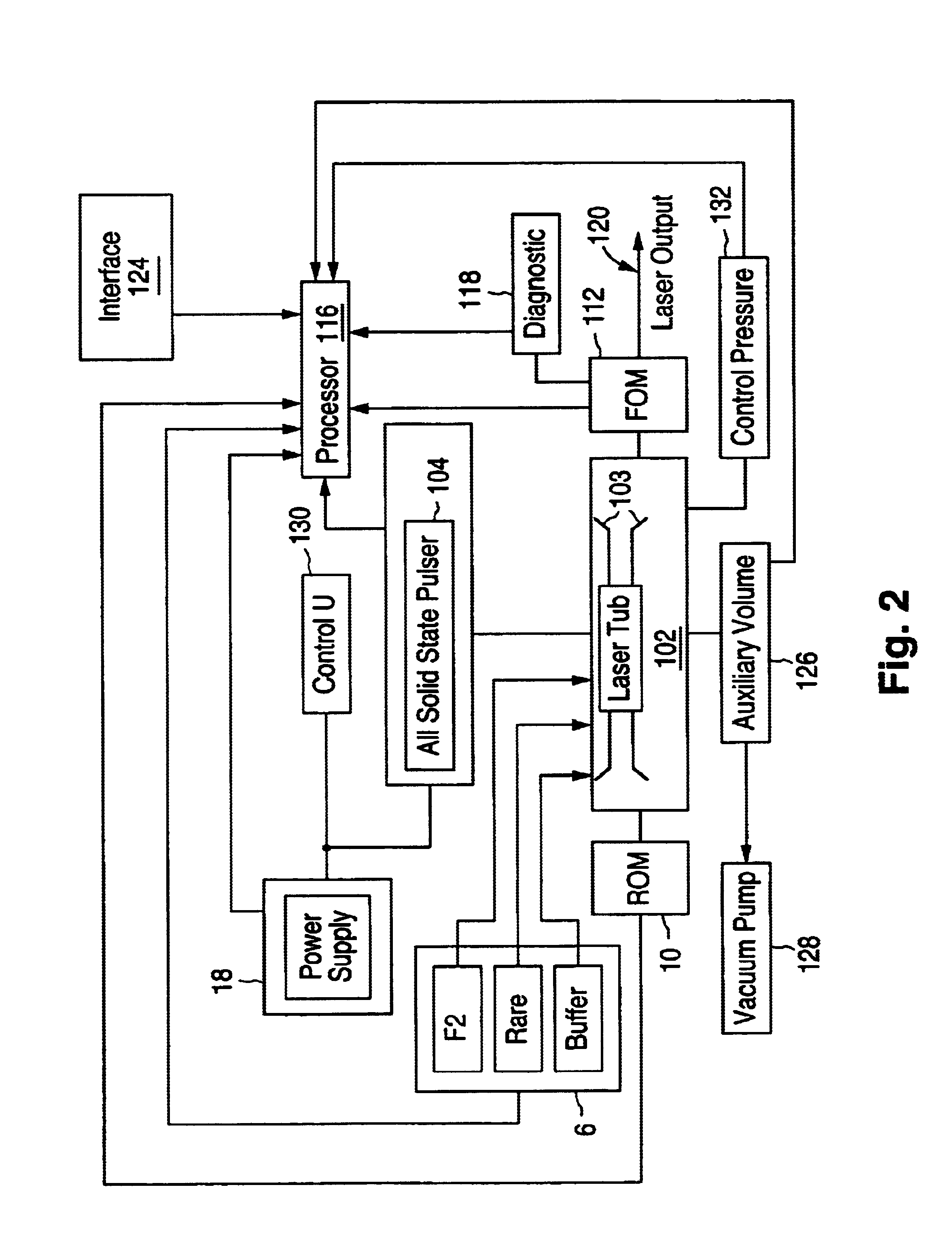
The preferred embodiments described below are drawn to a F.sub.2 laser having a variably adjustable total gas pressure for adjusting the bandwidth of the laser emission around 157 nm. A F.sub.2 laser is provided with a controlled total gas pressure, which is preferably below a typical excimer laser total laser tube gas pressure, for controlling the natural bandwidth of the laser emission around 157 nm, e.g., to substantially 0.5 pm or less. For example, the total pressure may be preferably below 2000 mbar and may be below 1500 mbar and may be below 1000 mbar. The F.sub.2 partial pressure is preferably maintained at a desired amount such as 50 to 100 mbar (5% F.sub.2 :95% Ne), or 2 to 5 mbar F.sub.2, while the remainder of the gas mixture is buffer gas. The total gas pressure is preferably controlled by controlling the partial pressure of the buffer gas in the gas mixture, wherein He and / or Ne is / are the preferred buffer gas or gases. Also preferably, the power or energy of the narro...


PUM


Abstract

A molecular fluorine laser system includes a discharge tube filled with a gas mixture including molecular fluorine and at least one buffer gas and having a total pressure of less than substantially 2500 mbar, multiple electrodes within the discharge tube, a pulsed discharge circuit connected to the electrodes for energizing the gas mixture, a line-selection optic for selecting one of multiple closely-spaced lines around 157 nm emitted from the discharge tube, and a laser resonator including the line-selection optic and the discharge tube for generating a beam of laser pulses having a wavelength around 157 nm at a bandwidth of less than 0.6 pm.

Description

1. Field of the InventionThe present invention relates to a method for adjusting the bandwidth of a natural or line-narrowed emission line of a F.sub.2 laser (e.g., .lambda..sub.1 =157.63094 nm) by adjusting the gas mixture to a selected composition.2. Discussion of the Related ArtLine-narrowing is an important feature of excimer laser systems being used for optical lithography. Commonly the bandwidth of the natural emission of the DUV or VUV laser being used is too broad to be used with projection illumination systems. A very small bandwidth is especially valuable when using high numerical aperture (NA) refractive imaging systems, wherein bandwidths below 1 pm are desired when the NA of the projection lens is very high, such as 70 or more. Line-narrowing of natural emission lines of excimer lasers is usually done by sophisticated dispersive arrangements within the laser resonator. For example, line-narrowing of the natural emission of the ArF laser is shown in U.S. Pat. No. 5,901,1...

Claims


Application Information

Patent Timeline
IPC IPC(8): H01S3/14H01S3/22H01S3/1055H01S3/08H01S3/134H01S3/036H01S3/106H01S3/105H01S3/038
CPCH01S3/22H01S3/036H01S3/038H01S3/08004H01S3/08009H01S3/1055H01S3/106H01S3/134H01S3/2258H01S2301/02
Inventor GOVORKOV, SERGEIVOGLER, KLAUSPAETZEL, RAINER
Owner LAMBDA PHYSIK
Why Eureka
Try Eureka