Supercharge Your Innovation With Domain-Expert AI Agents!

Lead seal assembly

a technology of lead seals and components, applied in the direction of identification means, screws, instruments, etc., can solve problems such as opening the way to fraud, and achieve the effect of reducing the possibility quite a bi

Inactive Publication Date: 2004-07-20
ACTARIS SAS
View PDF25 Cites 25 Cited by
  • Summary
  • Abstract
  • Description
  • Claims
  • Application Information

AI Technical Summary

Benefits of technology

The present invention makes it possible to reduce quite considerably the possibility of this type of situation by not giving installation and maintenance personnel sealing devices suitable for making a seal on the user's premises, but instead giving them devices that are factory-sealed and ready for mounting in a manner that is not reversible without breaking the seal.
This assembly presents the advantage of enabling the material used for sealing purposes, usually lead, to be replaced with brass, aluminum, or plastic.
Performing the sealing operation in a factory makes it possible firstly to use machines that are more sophisticated than a pair of pliers, so each seal can be marked with information such as: serial number; identity of distributor or installer; . . . . This makes it possible to keep a record of and to trace all seals made in this way.
Compared with traditional devices, this sealing device presents the advantage of being capable of using ordinary screws that are not pierced by a bore.

Problems solved by technology

In addition, since lead is a soft material, it remains possible to open a seal without damaging the seal in visible manner, thereby opening the way to fraud.

Method used


Image

  • Lead seal assembly
  • Lead seal assembly
  • Lead seal assembly

Examples


Embodiment Construction

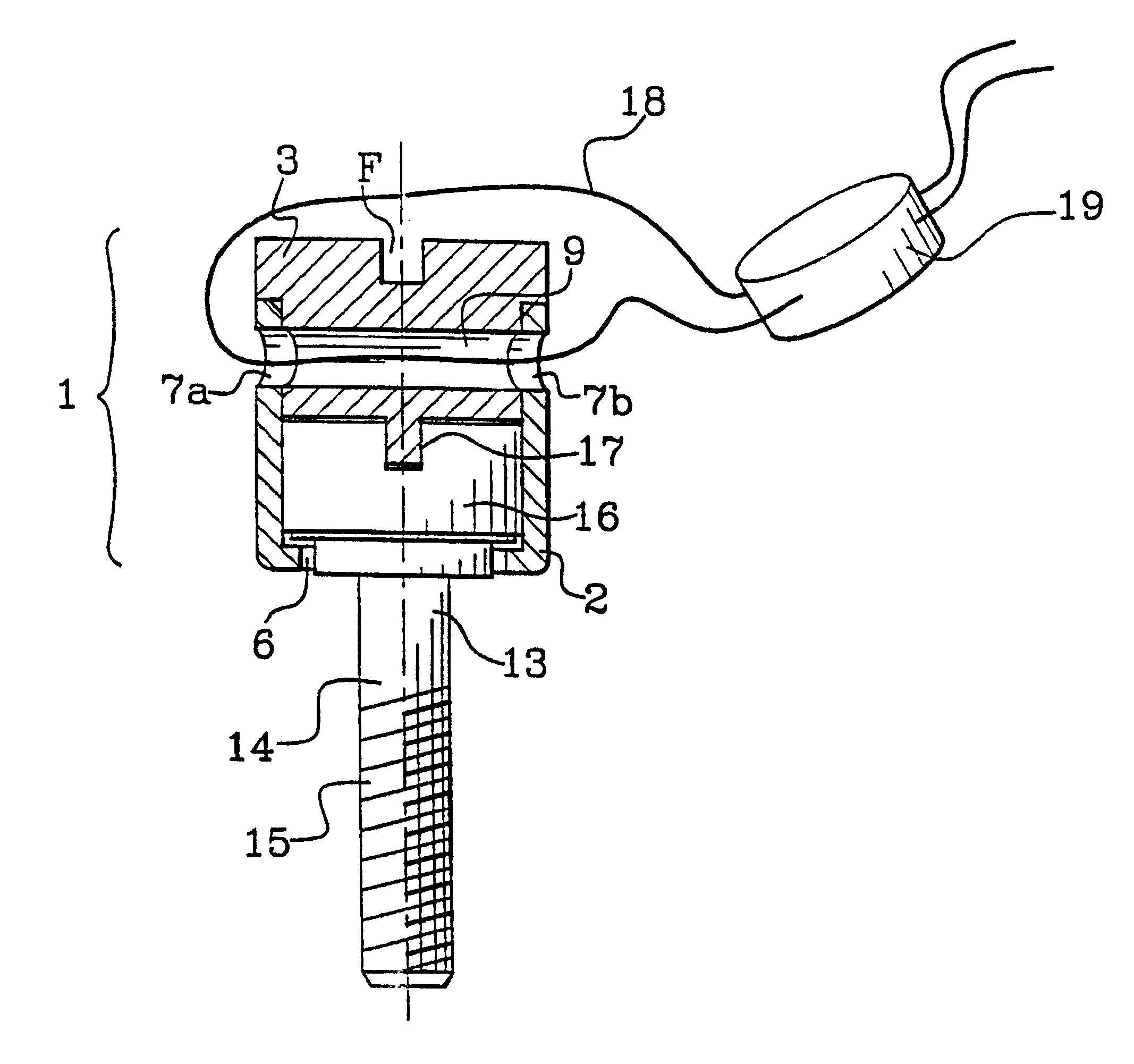
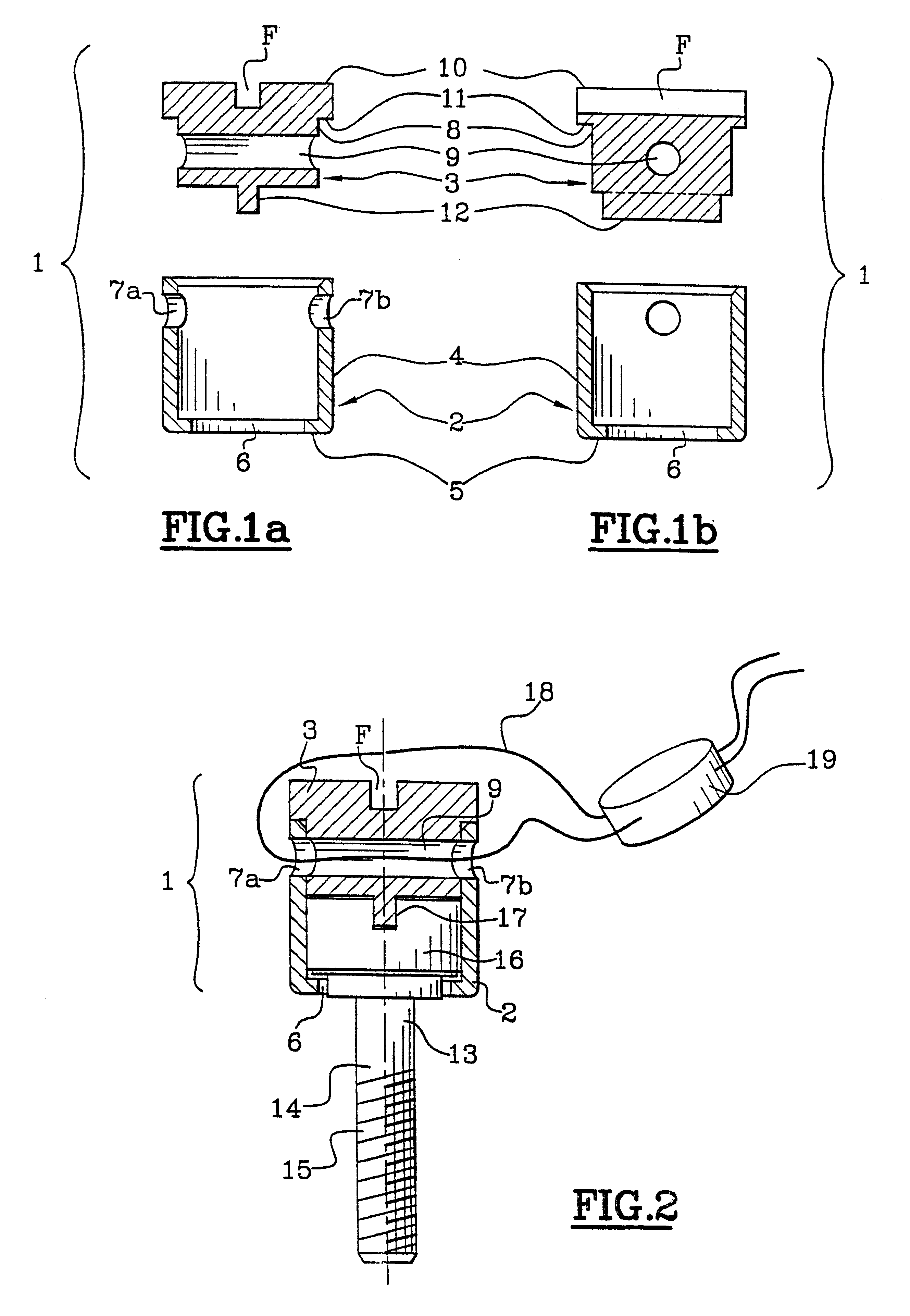
FIGS. 1a and 1b are diagrams of a sealing assembly 1 of the invention constituted by a first piece 2 in the form of a bushing and a closure piece 3, which pieces are suitable for co-operating with each other. The first piece can be made of aluminum, brass, stamped or turned steel, or indeed of molded plastics material. The closure piece can be made of alpax or any other injected aluminum alloy, of aluminum, of turned brass, or indeed of molded plastics material.

The first piece 2 is constituted by a side wall 4 and an end wall 5. The end wall is pierced by an opening 6 to allow the shank of a screw (not shown in FIGS. 1a and 1b) to be passed through, with the side wall 10 then forming a receptacle suitable for receiving the head of the screw.

The side wall 4 has through means 7a and 7b for passing a sealing wire (not shown in FIGS. 1a and 1b) said means being formed by two diametrically opposite openings in the top portion of the side wall 4.

The closure piece 3 has a bottom portion 8 ...


PUM


Abstract

A sealing assembly designed to co-operate with a screw provided with a tightening slot by being mounted therein in such a manner that once said assembly is sealed the tightening slot is hidden in a manner that is not reversible except by destroying the seal, and further comprising a breakable drive suitable when the sealing assembly is subjected to a tightening action, for driving the screw in a tightening direction inside a receptacle provided for this purpose and for breaking once the screw becomes blocked, so as to prevent any loosening action being applied via the breakable drive.

Description

The present invention relates to a sealing assembly which is advantageously applicable in meters, e.g. water, gas, electricity or heat meters. It also relates to a sealing device including such an assembly and to a meter including such a device.In general, it is desired to ensure that an apparatus is kept safe when the apparatus is in the possession of a user who might seek to dismantle it for dishonest purposes. This applies in particular to meters for water, gas, electricity, or heat, where such meters are generally protected by seals.Seals are known that are constituted by metal wires passing through a sealing device co-operating with the apparatus in question and having a metal endpiece at their ends, which endpiece is usually made of lead.As a general rule, with electricity meters, sealing devices are used to seal the covers or terminal caps of the meter to their supports. Traditionally, the head of a screw is pierced by a diametral bore, and after the screw has been tightened,...

Claims


Application Information

Patent Timeline
IPC IPC(8): G07C7/00F16B41/00G09F3/03
CPCG07C7/00G09F3/0317Y10T292/51Y10T292/48
Inventor GUILLON, JEAN-LOUIS
Owner ACTARIS SAS
Features
  • R&D
  • Intellectual Property
  • Life Sciences
  • Materials
  • Tech Scout
  • Unparalleled Data Quality
  • Higher Quality Content
  • 60% Fewer Hallucinations
Learn More