Sewer line pumping system

a technology of pumping system and sewer line, which is applied in the field of cleaning bodies, can solve the problems that the centrifugal pump arrangement after the settling container has not been used in the field of sewer cleaning apparatus, and achieve the effect of reducing the potential for wear

Inactive Publication Date: 2004-07-20
NEZAT II MALVIN A
View PDF35 Cites 8 Cited by
  • Summary
  • Abstract
  • Description
  • Claims
  • Application Information

AI Technical Summary

Benefits of technology

Unlike the prior art devises, having the pump in the fluid flow path after at least some of the solids separated or precipitated from the slurry reduces the potential for wear of or damage to the pump that draws the fluid or slurry through the separation system.

Problems solved by technology

However, such a centrifugal pump arrangement after the settling container has not been used in the field of sewer cleaning apparatus.

Method used


Image

  • Sewer line pumping system
  • Sewer line pumping system

Examples


Embodiment Construction

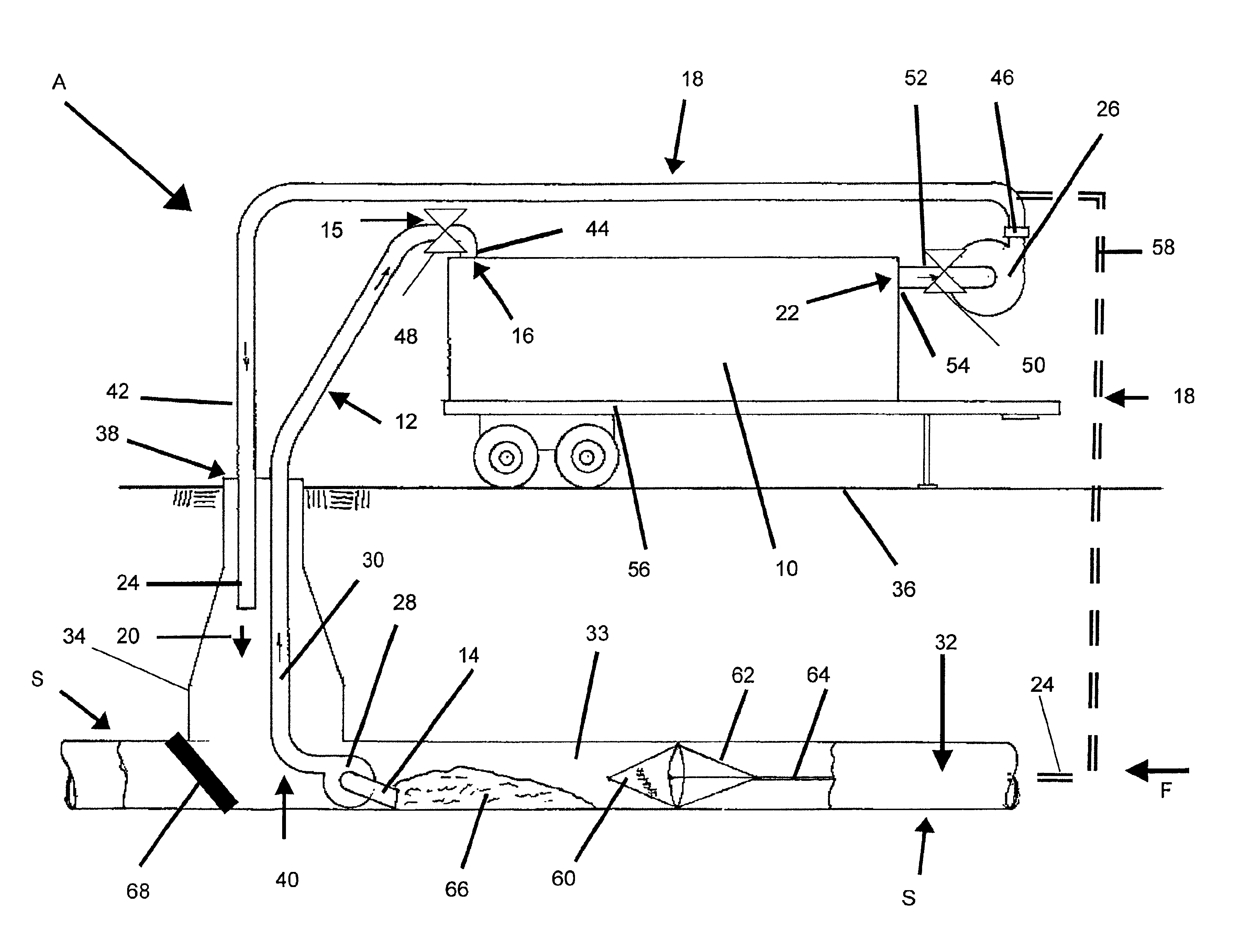
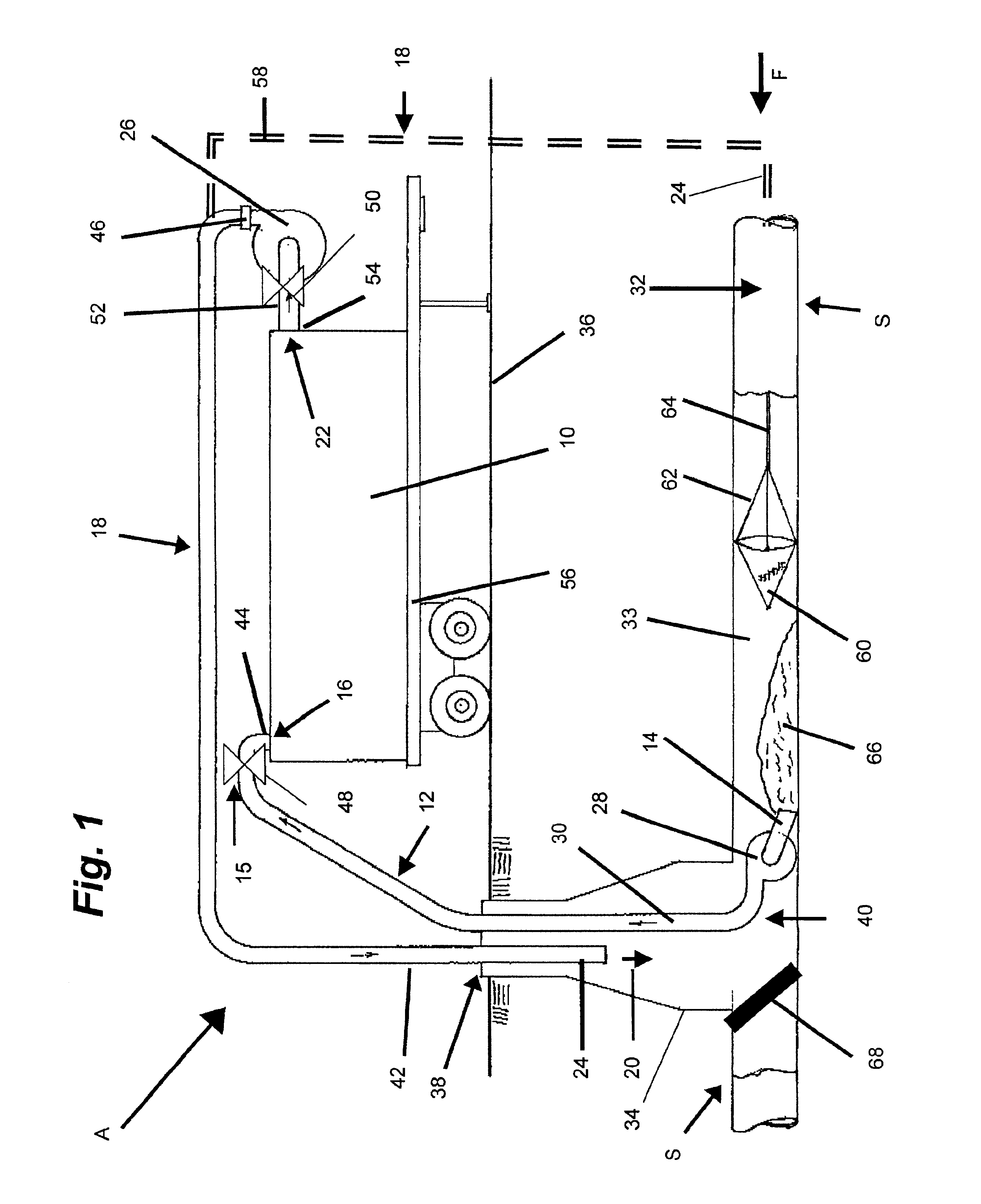
So that the manner in which the above recited features, advantages and objects of the present invention are attained can be understood in detail, more particular description of the invention, briefly summarized above, may be had by reference to the embodiment thereof that is illustrated in the appended drawings. In all the drawings, identical numbers represent the same elements.

A separation apparatus (A) for separating solids from a slurry of liquid and solids of the type found in sewers (S), ponds, or tanks includes a separation tank (10). An intake assembly (12) communicates with the separation tank (10) for conveying the slurry through a tank entrance end (15) into an inlet (16) formed in the tank (10). An outlet assembly (18) communicates with the separation tank (10) for conveying decanted liquid (20) in an outlet fluid flow line (42) through an outlet (22) formed in the tank (10) to an exit end (24) of the outlet assembly (18) positioned in a desired location. A main or primar...


PUM

PropertyMeasurementUnit
abrasiveaaaaaaaaaa
flexibleaaaaaaaaaa
flexibilityaaaaaaaaaa

Abstract

A separation apparatus (A) for separating solids from a slurry of liquid and solids includes a separation tank (10). An intake assembly (12) communicates with the separation tank (10) for conveying the slurry through an entrance end (14) into an inlet (16) formed in the tank (10). An outlet assembly (18) communicates with the separation tank (10) for conveying decanted liquid (20) through an outlet (22) formed in the tank (10) to an exit end (24) of the outlet assembly (18) positioned in a desired location. A pump (26) is adapted to convey the decanted liquid (20) from the separation tank (10) through the outlet assembly (18). The tank (10), intake assembly (12), and outlet assembly (18) form an airtight, compartmented system when the entrance end (14) of the intake assembly (12) and the exit end (24) of the outlet assembly (18) are sealed.

Description

1. Technical FieldThe invention relates to the field of cleaning bodies of liquid slurries or waste collection systems, such as sewer lines, collection tanks, and in particular to cleaning and removing of solid and liquid materials therefrom.2. Background ArtSeparation systems are used generally by commercial sewer cleaning services for removing unwanted solids from a liquid slurry mixture found in sewer lines to unclog sewer lines or to increase fluid flow that has been restricted due to sediments forming in the sewer line or other debris clogging the pipeline.Apparatus for cleaning sewers are known. For example, U.S. Pat. No. 5,068,940 teaches a truck mounted sewer cleaning system having the pump that moves the liquid slurry through the system ahead of the separation box in which solids are separated from the slurry.Other known sewer cleaning systems use a centrifugal separator to separate solids from the liquid slurry. The centrifugal separators are utilized to separate the solid...

Claims


Application Information

Patent Timeline
Patent Type & Authority Patents(United States)
IPC IPC(8): B01D21/00
CPCB01D21/0018B01D21/02B01D21/2416B01D21/2444
Inventor NEZAT, II, MALVIN A.
Owner NEZAT II MALVIN A
Why Eureka
Try Eureka