Ultrasonic horn with isotropic breathing characteristics

a technology of ultrasonic horn and isotropic breathing, applied in the field of ultrasonic horn, can solve the problems of non-uniform bonding or other work, component failure to even operate, non-uniform expansion and contraction,

Inactive Publication Date: 2004-07-27
DUKANE IAS LLC
View PDF18 Cites 38 Cited by
  • Summary
  • Abstract
  • Description
  • Claims
  • Application Information

AI Technical Summary

Problems solved by technology

The amount of energy transferred to respective work pieces therefore varies, and non-uniform bonding or other work can result.
Under certain operating conditions more than one of these modes can be manifested, resulting in non-uniform expansion and contraction.
In some instances where a large number of modes are coupled, the component may not even operate, rendering it scrap.

Method used


Image

  • Ultrasonic horn with isotropic breathing characteristics
  • Ultrasonic horn with isotropic breathing characteristics
  • Ultrasonic horn with isotropic breathing characteristics

Examples


Embodiment Construction

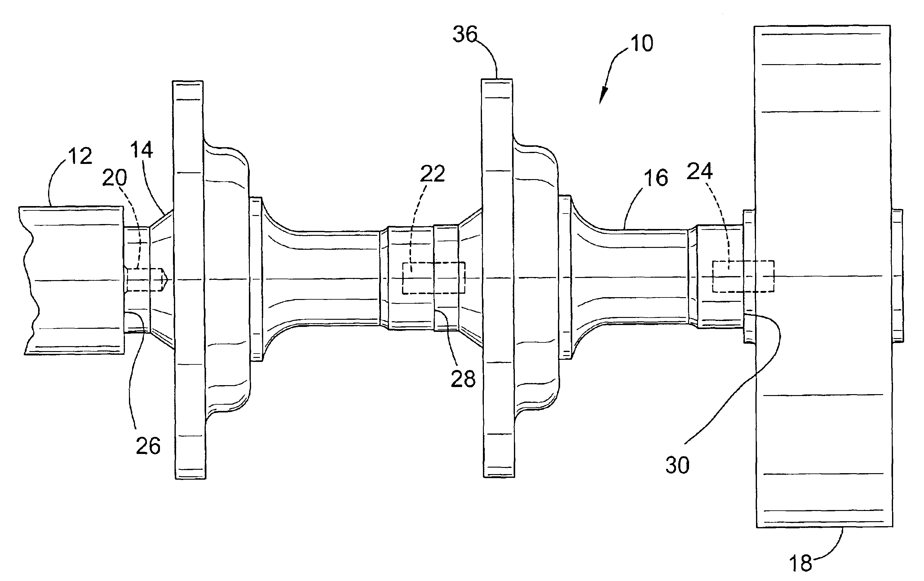
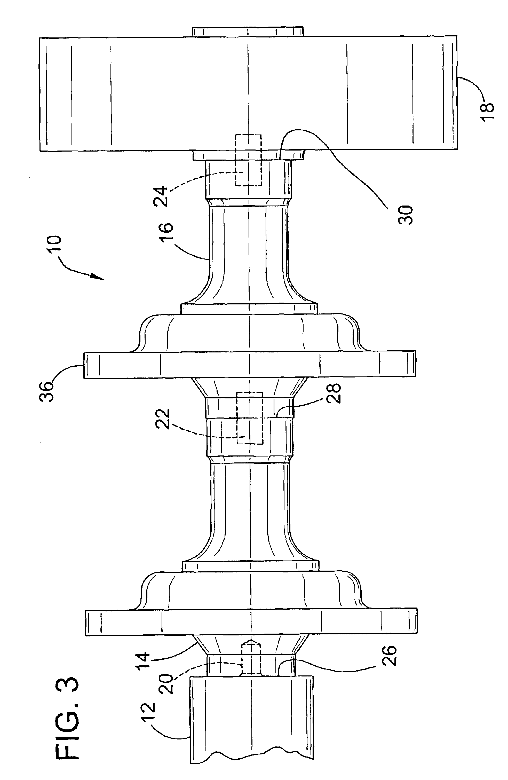
An ultrasonic rotary horn of the invention having a HIP-consolidated microstructure with generally random isotropic grain alignment was tested at 20,000 Hz to determine the variation in its amplitude of expansion and contraction, i.e., whether it expands and contracts generally uniformly and isotropically in all radial directions. An ultrasonic rotary horn having a forged microstructure was similarly tested for comparison. Each horn was assembled into a rotary horn stack assembly having the horn, a 1.5-gain Dukane booster (Part 110-2512), and a Dukane converter (Part 110-3716-001). Each horn was energized and the frequency was permitted to stabilize to plus or minus about 5 Hz. An amplitude sensor probe (Kaman Instrumentation Corp., Middletown, Conn., Part No. KD-4200) was applied to measure the amplitude of displacement of the horn adjacent a first edge, and the horn was rotated so an amplitude reading was taken every 15 degrees of rotation. After the entire circumference was measu...


PUM

PropertyMeasurementUnit
frequencyaaaaaaaaaa
frequencyaaaaaaaaaa
operating frequencyaaaaaaaaaa

Abstract

An ultrasonic horn having substantially uniformly isotropic radial expansion and contraction amplitude in all radial directions upon excitation. The horn has a microstructure characterized by isotropically random directional grain alignment. A method for manufacturing a horn.

Description

BACKGROUND OF INVENTIONThis invention relates to an ultrasonic horn for use in manufacturing operations such as bonding, perforation, and cutting.Ultrasonic horns are used to distribute ultrasonic energy in a variety of industrial processes. One example involves bonding of two thermoplastic sheets of material together in the manufacture of personal care products such as diapers.Ultrasonic horn assemblies can have a number of distinct components, which can be connected in a stack. In one arrangement, these components may include a power excitation device known as a converter (or driver assembly), amplitude modification devices known as boosters, and an ultrasonically energized tool known as an ultrasonic horn, which contacts a work piece.Upon energization ultrasonic horns cyclically expand and contract, which expansion and contraction is the driving force for the bonding or other mechanical operation performed by the horn. For example, a horn may expand and contracts a total amplitud...

Claims


Application Information

Patent Timeline
Patent Type & Authority Patents(United States)
IPC IPC(8): B06B3/00B22F3/15B22F3/14B29C65/08
CPCB06B3/00B22F3/15B29C65/085B29C66/83411B29C66/9513B22F2998/00B29C66/9517Y10T156/1741B29L2031/4878B29C65/087B29C66/83413Y10T29/4998B29C66/81241B29C66/73921B29C66/41
Inventor STEGELMANN, NORMAN R.
Owner DUKANE IAS LLC
Why Eureka
Try Eureka