High frequency and low frequency audio signal encoding and decoding system

a high frequency and low frequency audio signal and audio signal technology, applied in the field of transmission systems, can solve the problem that the coding device needs to have considerable computation capacity

Inactive Publication Date: 2004-08-03
KONINKLJIJKE PHILIPS NV
View PDF7 Cites 120 Cited by
  • Summary
  • Abstract
  • Description
  • Claims
  • Application Information

AI Technical Summary

Benefits of technology

It is an object of the invention to provide a transmission system in which the necessary computation capacity is reduced.

Problems solved by technology

A disadvantage of such a transmission system is that the coding device needs to have considerable computation capacity for the splitting up of the input signal into spectral portions by a filter bank in the transmitter and the combining of the spectral portions in the receiver with the aid of a combiner.

Method used


Image

  • High frequency and low frequency audio signal encoding and decoding system
  • High frequency and low frequency audio signal encoding and decoding system
  • High frequency and low frequency audio signal encoding and decoding system

Examples


Embodiment Construction

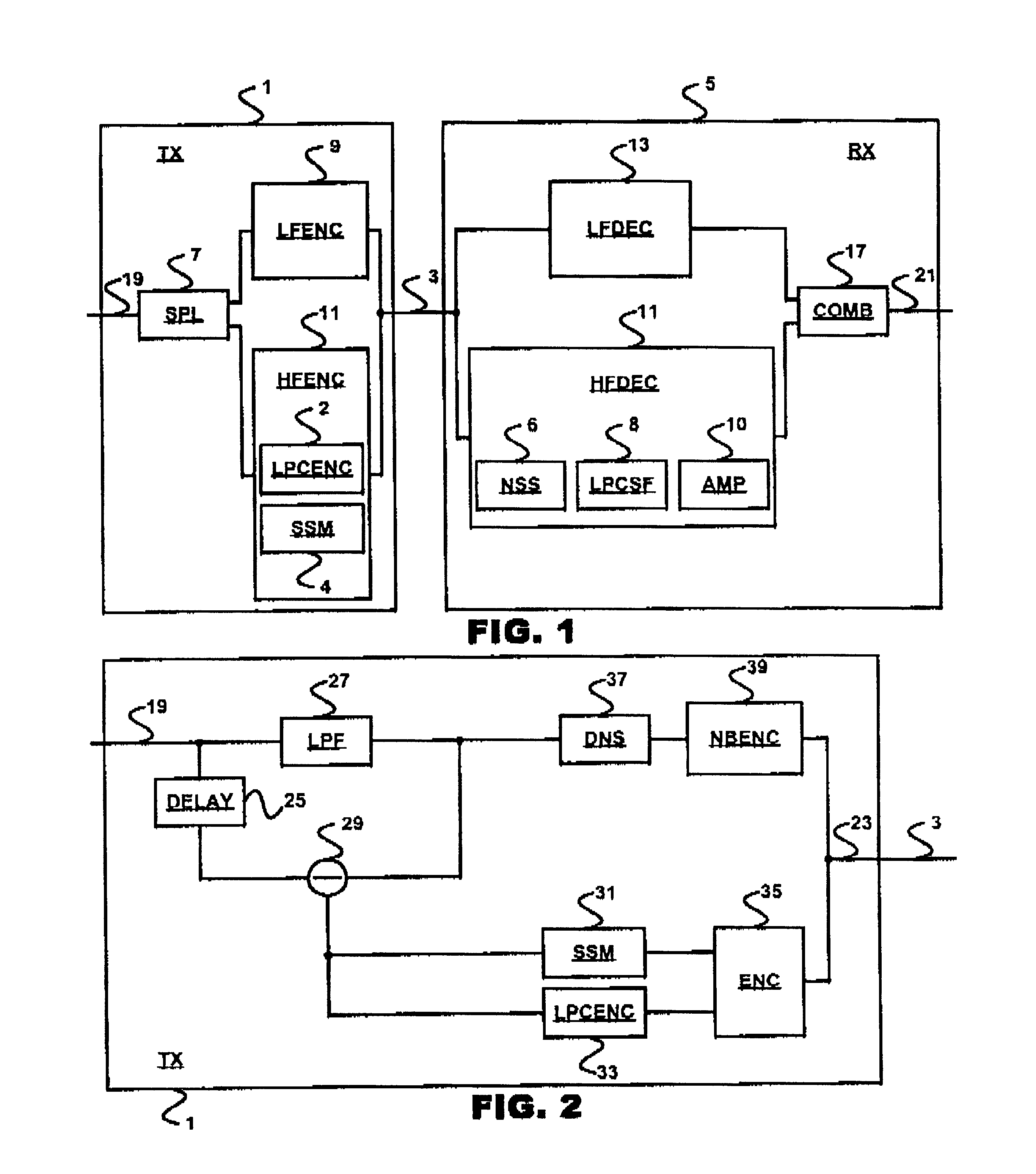
FIG. 1 diagrammatically shows a transmission system according to the invention.

The input signal arrives through an input 19 of a transmitter ("TX") 1. A splitter ("SPL") 7 splits up the input signal 19 into a signal that has a low frequency range and is processed by a first coder ("LFENC") 9, and a signal that has a high frequency range and is processed by a second coder ("HFENC") 11, the second coder 11 utilizing an LPC coder ("LPCENC") 2 and a signal strength meter ("SSM") 4. The coder 11 is an LPC coder, which determines prediction coefficients of the signal that has a high frequency range. The coded signals appear on the output of the first coder 9 and the second coder 11 and are transmitted to a receiver ("RX") 5 by a transmission channel 3. In this receiver 5, the coded signal having a low frequency range is processed by a first decoder ("LFDEC") 13 and the coded signal having a high frequency range is processed by a second decoder ("HFDEC") 15, while use is made of a noise si...


PUM


Abstract

In an audio transmission system, an input signal is split up into two spectral portions in a transmitter. These spectral portions are coded by their own respective coder. The low-frequency signal portion is coded by a regular narrow-band coder and the high frequency portion is coded using a coder that outputs LPC codes and signal amplitude codes. In the receiver, the low frequency signal portion is reconstructed by a narrow-band decoder and the high frequency portion is reconstructed by applying a high pass filter to a white noise signal and applying an LPC filter that is controlled by the LPC codes to this filtered white noise signal and adjusting the signal amplitude with an amplifier that is controlled using the amplitude codes of the transmitter. The reconstructed low frequency signal and the reconstructed high frequency signal are then combined to yield a reconstructed output signal containing both frequency ranges.

Description

1. Field of the InventionThe invention relates to a transmission system employing a transmitter including a splitter for splitting up a transmission signal into a signal having a low frequency range and a signal having a high frequency range, and a first coding device for deriving a coded signal having a low frequency range from the signal having a low frequency range. The first coding device is arranged for transmitting the coded signal having a low frequency range to a receiver by a first transmission channel. The receiver employs a first decoder for forming a reconstructed signal having a low frequency range based on the coded signal having a low frequency range. The transmitter further employs a second coding device for deriving a coded signal having a high frequency range from the signal having a high frequency range, which second coding device is arranged for transmitting the coded signal having a high frequency range from the transmitter to the receiver by a second transmissi...

Claims


Application Information

Patent Timeline
Patent Type & Authority Patents(United States)
IPC IPC(8): G10L19/00G10L19/02G10L21/02H03M7/30
CPCG10L19/0208H04B1/04
Inventor SLUIJTER, ROBERT JOHANNESGERRITS, ANDREAS JOHANNESTAORI, RAKESHCHENNOUKH, SAMIR
Owner KONINKLJIJKE PHILIPS NV
Why Eureka
Try Eureka