Laser device for guiding a vehicle

a laser device and vehicle technology, applied in the field of guidance systems, can solve the problems of trailer contact, driver's inability to determine the clearance around these structures, and many people are uncomfortable driving through long tunnels, and achieve the effect of simple structur

Inactive Publication Date: 2004-08-10
NEWCOMER RONALD E
View PDF32 Cites 10 Cited by
  • Summary
  • Abstract
  • Description
  • Claims
  • Application Information

AI Technical Summary

Benefits of technology

It is therefore an object of this invention to overcome the disadvantages of the above noted devices and provide a guide system for guiding a human driver down a road or through a tunnel or the like. It is still a further object to provide a guide system that is simple in structure and requires minimal additions to existing vehicles. It is another object to provide a guide system that does not interfere with the normal driving operations of the vehicle whether inside the tunnel or the like or outside on the open road.
The line rays may also be projected from other structures where it is desired that the vehicle travel directly down the center of the pathway, such as the roof of a toll booth. As vehicles would pull into the lane beside the booth, the line ray would project onto the hood of the vehicle. Large vehicles or vehicles pulling a boat or trailer could align the line ray with an indicator of the vehicle to assure that they are traveling down the middle of the lane. This could prevent the large vehicle or its trailer from contacting a barrier or wall of the toll booth due to the vehicle being off-center in the lane.

Problems solved by technology

Many people are uncomfortable driving through long tunnels, especially those having either poor lighting or those having unclear lane designations.
The drivers may be unable to determine clearance around these structures and may contact the walls or barriers.
While the vehicle itself may easily clear the structure, a small misalignment may cause the trailer to contact the toll-both barriers.
However, each of the apparatuses used in these inventions requires extensive detection means and computer-aided machinery to guide the driving device through the tunnel, which can be very expensive.
Additionally, once the vehicle exits the road, tunnel or hallway, the device becomes inoperative with the guide device.
Further, none of these references operates in conjunction with a human driver to guide them along the road.

Method used


Image

  • Laser device for guiding a vehicle
  • Laser device for guiding a vehicle
  • Laser device for guiding a vehicle

Examples


Embodiment Construction

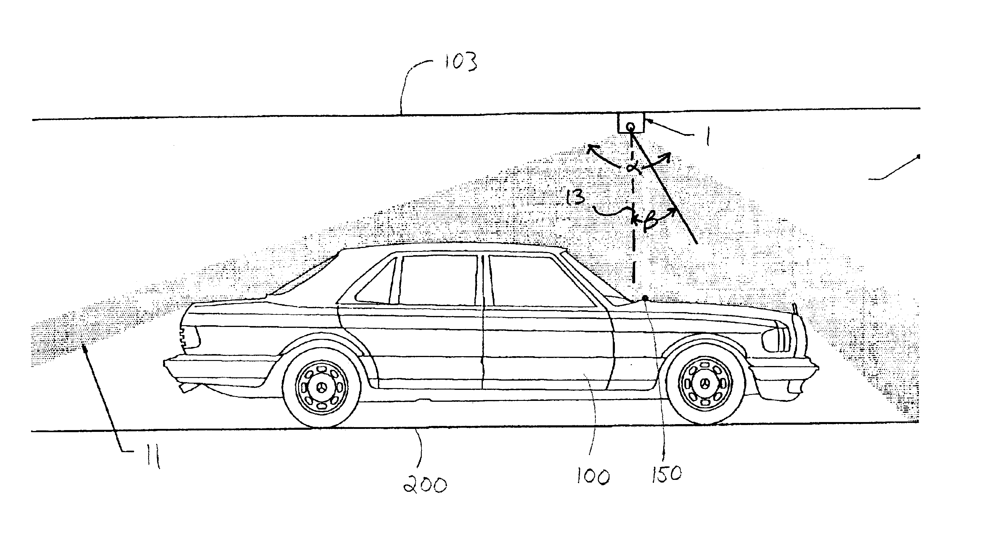
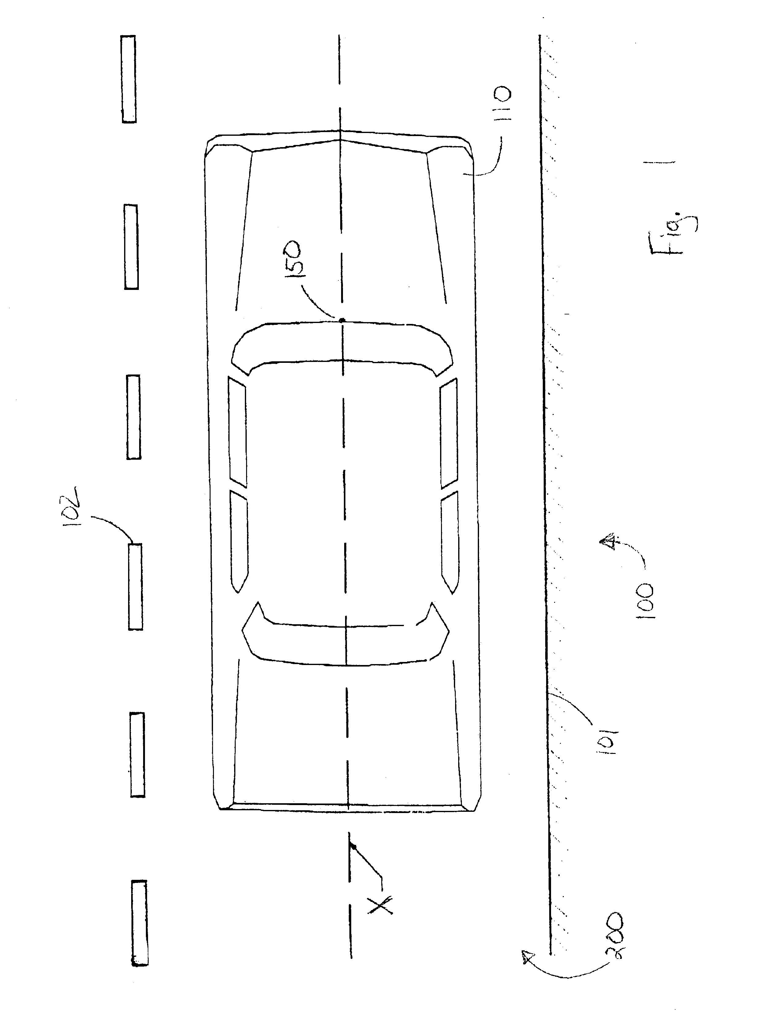
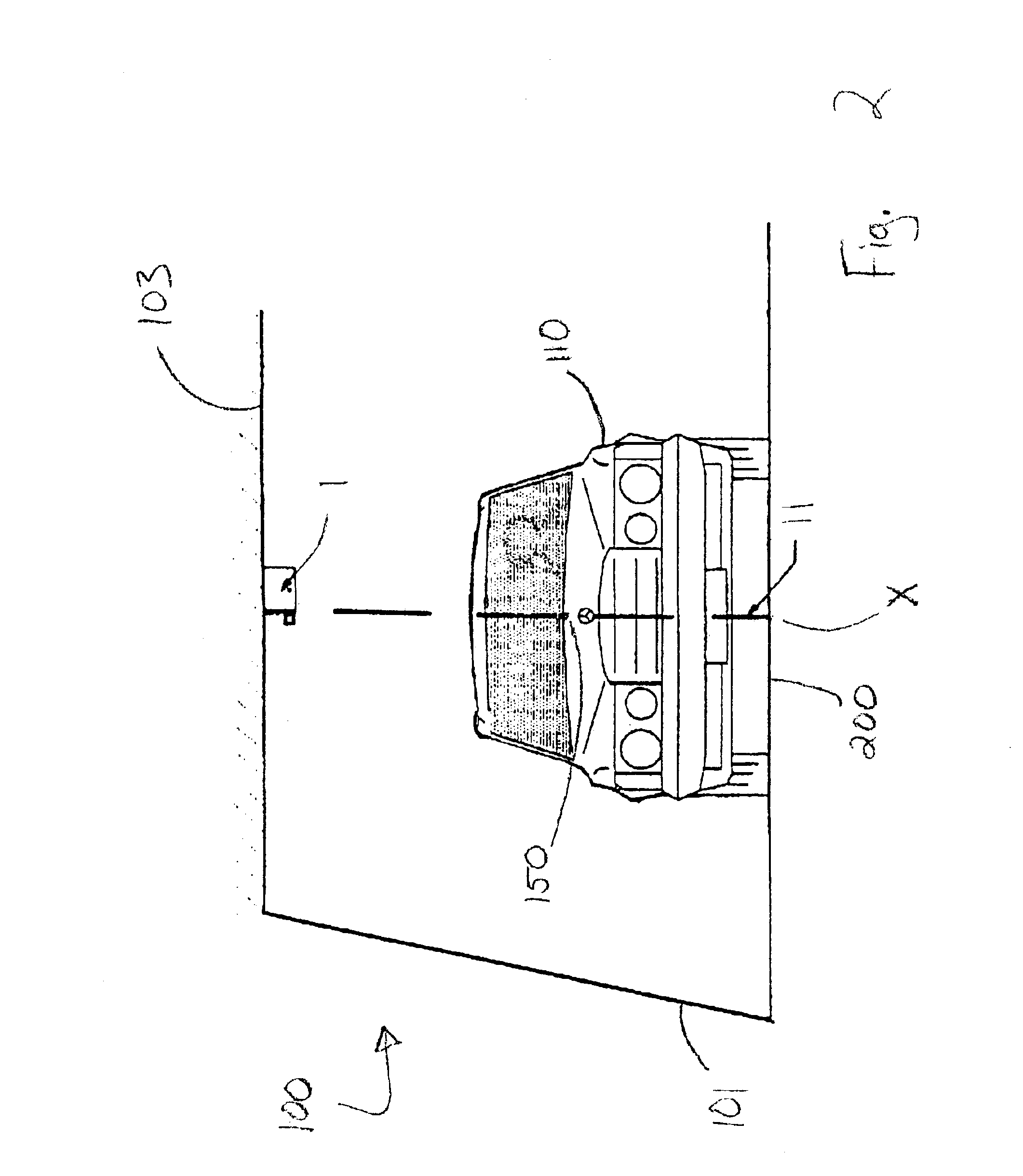
Referring to FIG. 1, there is shown a perspective view of a tunnel 100 with a vehicle 110 traveling thereon along a right hand lane 200 of a roadway. The right hand lane 200 is defined by a tunnel wall 101 and a center strip 102. A vehicle traveling through the tunnel would preferably travel down the center of the lane to prevent the vehicle from interfering with oncoming traffic on the other side of the roadway (not shown) and contacting objects near tunnel wall 101, such as a sidewalk railing, etc. The right hand lane 200 has a center line X which extends along the center thereon. Vehicle 110 traveling down the lane, to avoid the mentioned pitfalls, would travel with the center of any vehicle coinciding with center line X.

In order to aid vehicle 110 to travel along center line X, the vehicle has a spot 150 which is be used as the predetermined indicator. The spot in this embodiment is located along the center of vehicle 110 and at the point where the windshield and hood of the veh...


PUM


Abstract

A method and system for guiding a vehicle through a tunnel or other space. A linear beam of light is projected along a certain path through the space. As the vehicle travels into the space, the linear beam is shined upon the vehicle. Visually aligning an indicator on the vehicle with the linear beam of light indicates to the driver that the vehicle is traveling directly down the center of the path. The alignment occurs by the driver making manual adjustments of the vehicle's direction by turning wheels of the vehicle.

Description

BACKGROUND OF INVENTIONThis invention involves guidance systems to aid drivers in tunnels and the like to properly navigate a predetermined path along the length of the tunnel.Many people are uncomfortable driving through long tunnels, especially those having either poor lighting or those having unclear lane designations. The driver may veer from his / her lane and travel either into the opposite lane or into a curb or other structure on the side of the road. A similar situation also occurs with respect to other structures similar to tunnels, such as beside toll booths and other small through-passages. The drivers may be unable to determine clearance around these structures and may contact the walls or barriers. This is especially true for wider vehicles or those pulling large items, such as boats or trailers. While the vehicle itself may easily clear the structure, a small misalignment may cause the trailer to contact the toll-both barriers.The prior art discloses a wide variety of a...

Claims


Application Information

Patent Timeline
Patent Type & Authority Patents(United States)
IPC IPC(8): G01C15/00
CPCG01C15/00
Inventor NEWCOMER, RONALD E.
Owner NEWCOMER RONALD E
Why Eureka
Try Eureka