
System protection map

a system protection and map technology, applied in the field of microprocessors, can solve problems such as resource allocation problems, system operation may be dire, and use of memory or peripheral devices may have dire consequences for system operation

Inactive Publication Date: 2004-08-10
TEXAS INSTR INC
View PDF9 Cites 109 Cited by
  • Summary
  • Abstract
  • Description
  • Claims
  • Application Information

AI Technical Summary

Benefits of technology

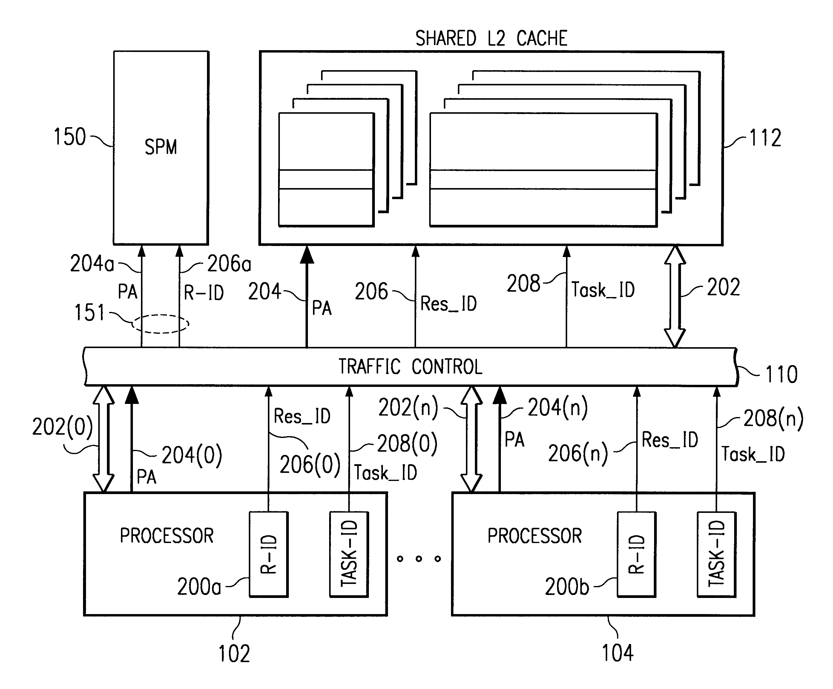
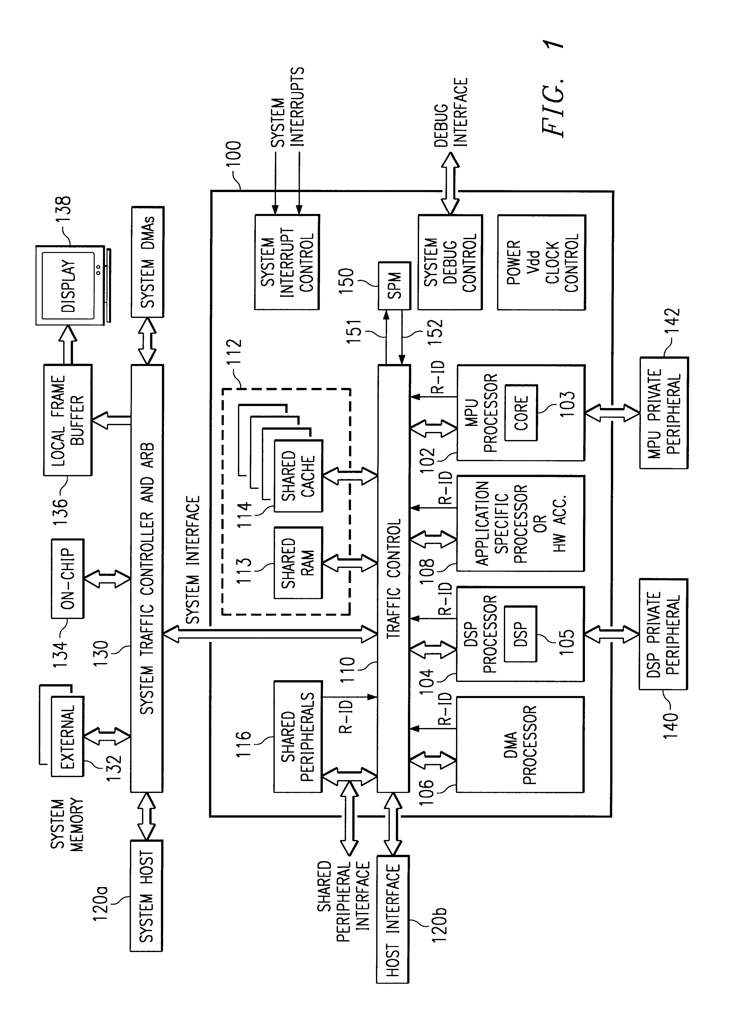
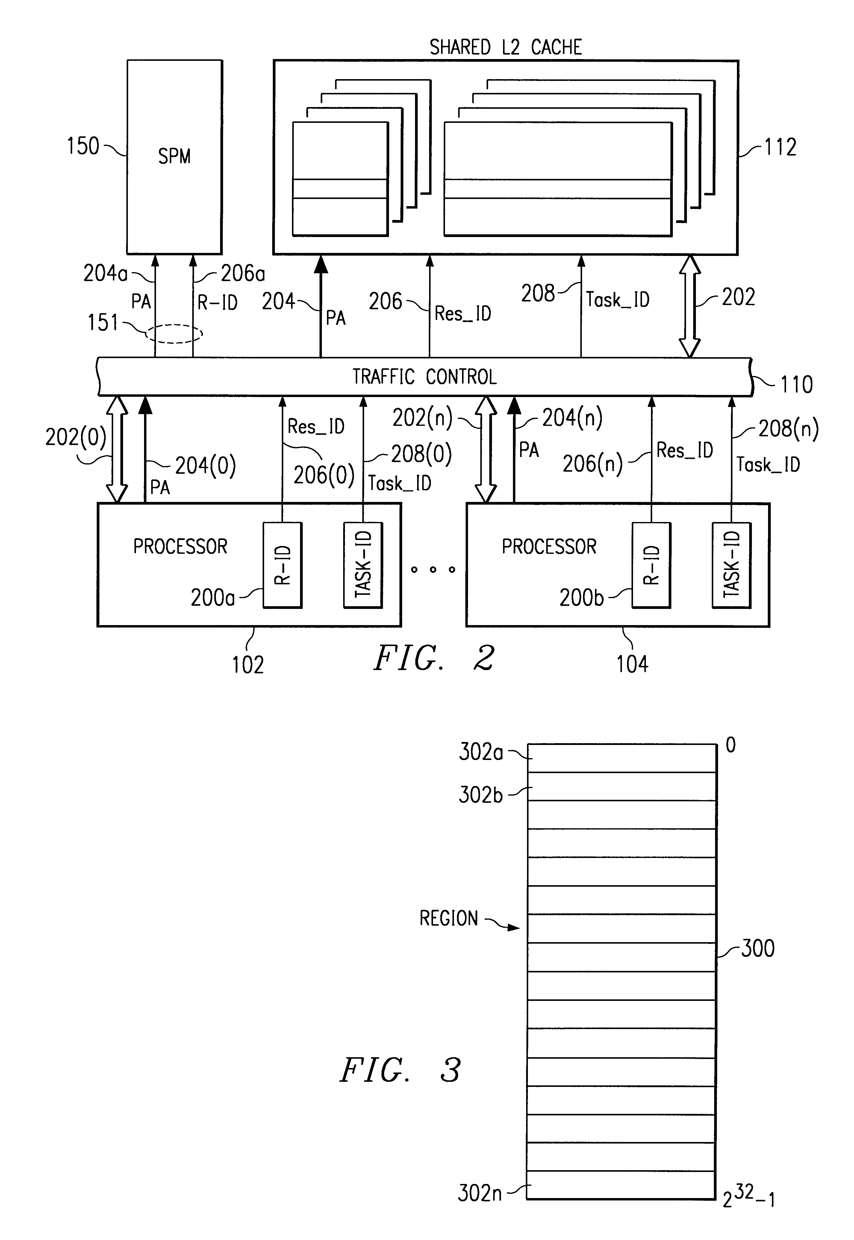
It has now been discovered that the OSs must cooperate in partitioning the system, either statically or dynamically. A system protection map (SPM) can then be used to ensure that the agreed upon partitioning is actually followed. An SPM doesn't necessarily supplant memory management facilities that are present on a given processor, but rather provides an additional level of protection in order to protect operation systems from each other.
In general, and in a form of the present invention, a method is provided for operating a digital system having a plurality of initiator resources including a plurality of processors connected to a shared memory subsystem. Two or more of the processors execute separate operating systems. In order to control access to shared resources, a plurality of regions within an address space of the memory subsystem is defined. Initiator resource access rights are assigned to at least a portion of the plurality of regions to indicate which initiator resource is allowed to access each region. Using the address provided with the access request, the region being acc...

Problems solved by technology

Many OSs were not designed in a manner to share memory and resources with another OS.
Therefore, when two or more OSs are combined in a single system, resource allocation problems may occur.
Conflicts over use of memory or peripheral devices may have dire consequences for system operation.

Method used


Image

  • System protection map
  • System protection map
  • System protection map

Examples


Embodiment Construction

System protection cannot prevent conflict, so to speak. If OS 1 on processor A and OS 2 on processor B both think they have total control of device D, then there is a problem. Protection doesn't really make that problem go away, it only detects failures of partitioning of the system. To be successful, the OS's must cooperate in partitioning the system, either statically or dynamically. A system protection map (SPM) can then ensure that the agreed upon partitioning is actually followed.

To partition statically, a system developer allocates resources (memory and devices) to each processor and this partitioning doesn't change during system operation. This works well in many embedded systems.

A more interesting situation is when the partitioning may be changed during operation. In this case, there must be a means of negotiation for system resources and a means of updating the SPM.

A partitioning is most interesting if there are some resources that may be shared between the two OSs and that...


PUM


Abstract

A method and apparatus is provided for operating a digital system having several processors (102, 104) and peripheral devices (106, 116) connected to a shared memory subsystem (112). Two or more of the processors execute separate operating systems. In order to control access to shared resources, a set of address space regions within an address space of the memory subsystem is defined within system protection map (SPM) (150). Resource access rights are assigned to at least a portion of the set of regions to indicate which initiator resource is allowed to access each region. Using the address provided with the access request, the region being accessed by a memory access request is identified by the SPM. During each access request, the SPM identifies the source of the request using a resource identification value (R-ID) provided with each access request and then a determination is made of whether the resource accessing the identified region has access rights for the identified region. Access to the identified region is allowed to an initiator resource only if the resource has access rights to the identified region, otherwise an error process is initiated (151).

Description

FIELD OF THE INVENTIONThis invention generally relates to microprocessors, and more specifically to improvements in memory access protection circuits, systems, and methods of making.BACKGROUND OF THE INVENTIONMicroprocessors are general-purpose processors that provide high instruction throughputs in order to execute software running thereon, and can have a wide range of processing requirements depending on the particular software applications involved. Many different types of processors are known, of which microprocessors are but one example. For example, Digital Signal Processors (DSPs) are widely used, in particular for specific applications, such as mobile processing applications. DSPs are typically configured to optimize the performance of the applications concerned and to achieve this they employ more specialized execution units and instruction sets. Particularly in applications such as mobile telecommunications, but not exclusively, it is desirable to provide ever-increasing D...

Claims


Application Information

Patent Timeline
IPC IPC(8): G06F12/14G06F12/00G06F12/10G06F15/16G06F15/167G06F15/177G06F21/62
CPCG06F12/1483G06F12/109H04W72/00G06F12/1063G06F12/1009
Inventor KRUEGER, STEVEN D.
Owner TEXAS INSTR INC
Learn More