
Device for measuring the mass of a flowing medium in an intake tube

a technology of a flow medium and a measurement conduit, which is applied in the direction of engine testing, structural/machine measurement, instruments, etc., can solve the problem of hollows in the side faces of the measurement condui

Inactive Publication Date: 2004-08-24
ROBERT BOSCH GMBH
View PDF14 Cites 26 Cited by
  • Summary
  • Abstract
  • Description
  • Claims
  • Application Information

AI Technical Summary

Benefits of technology

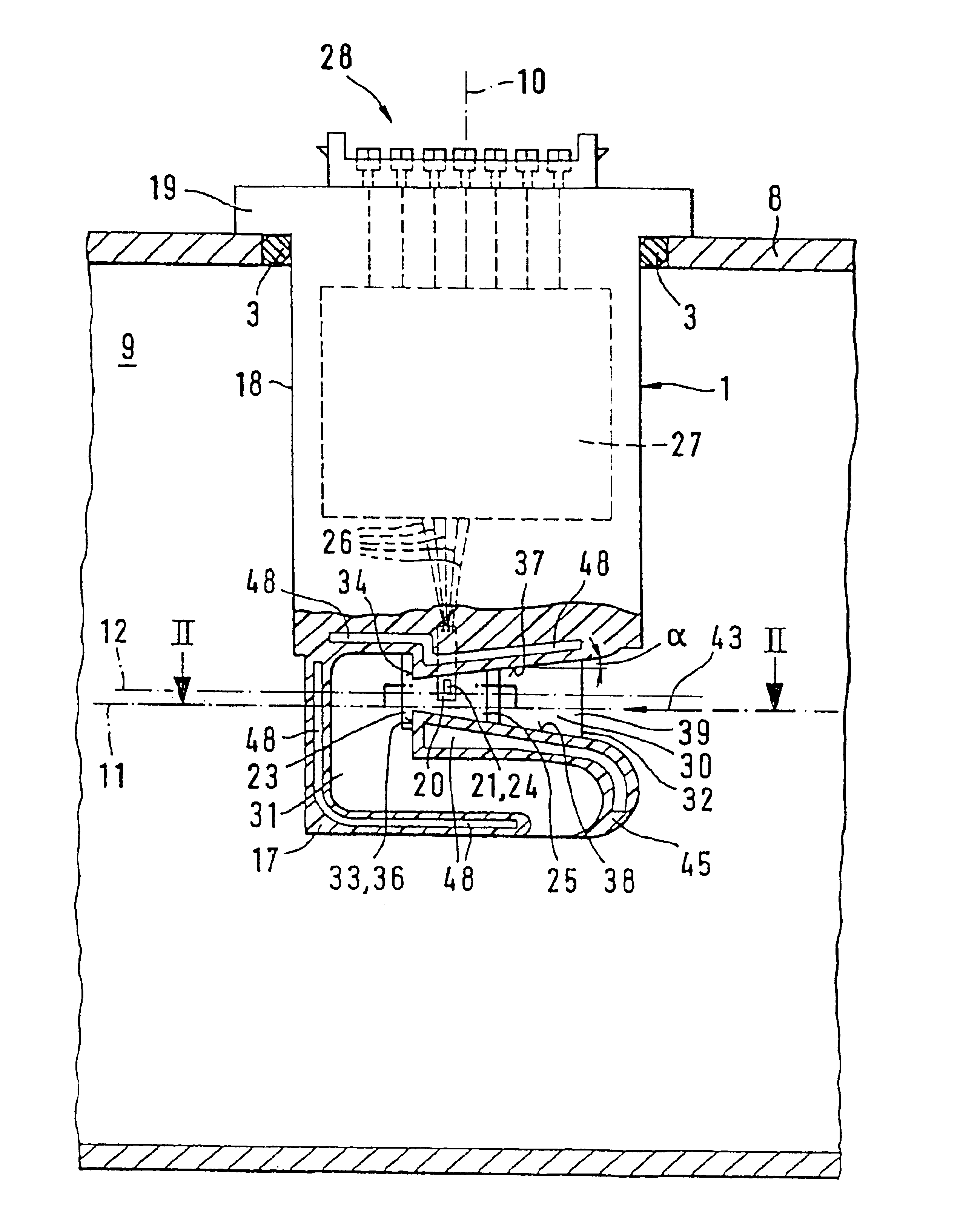
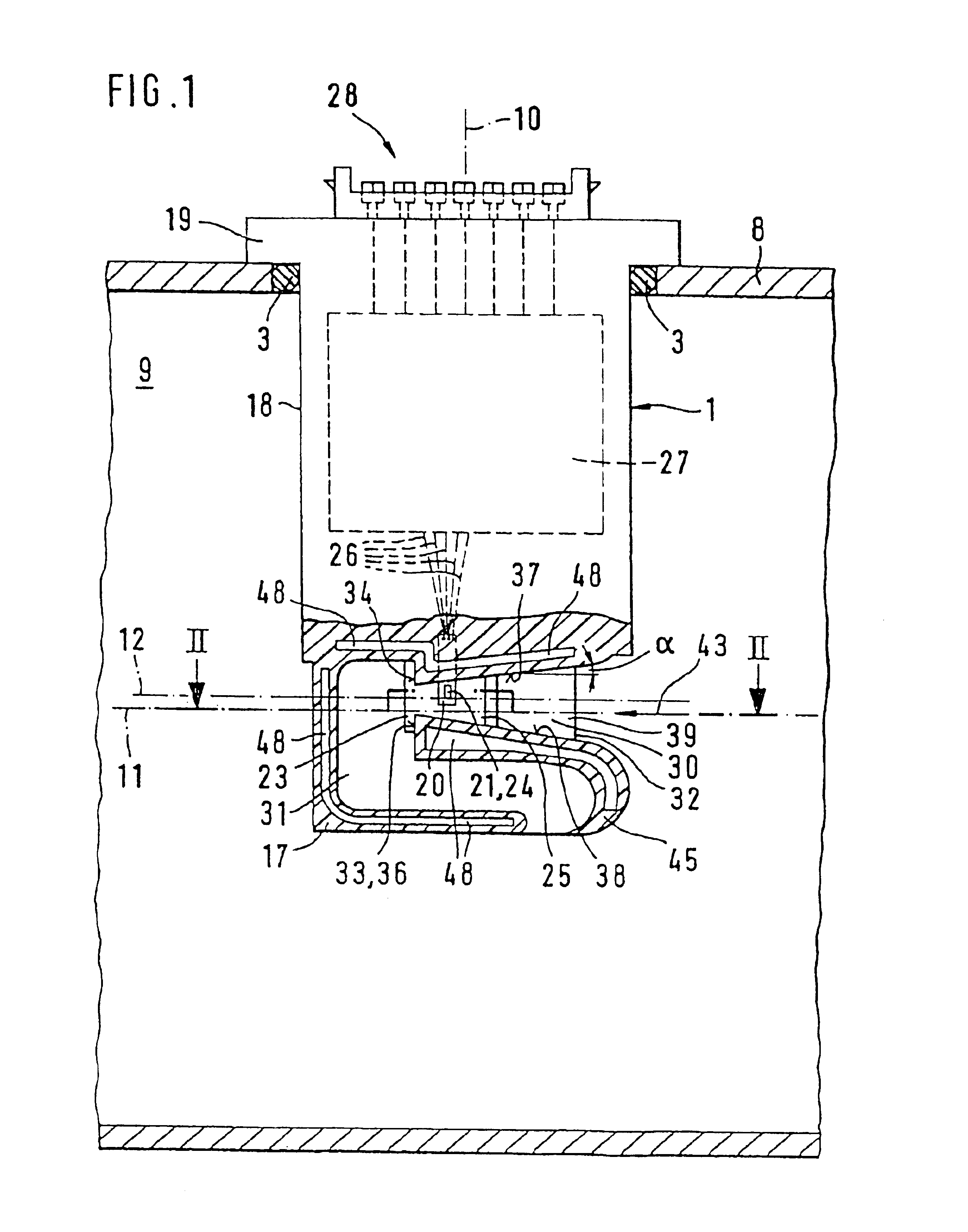
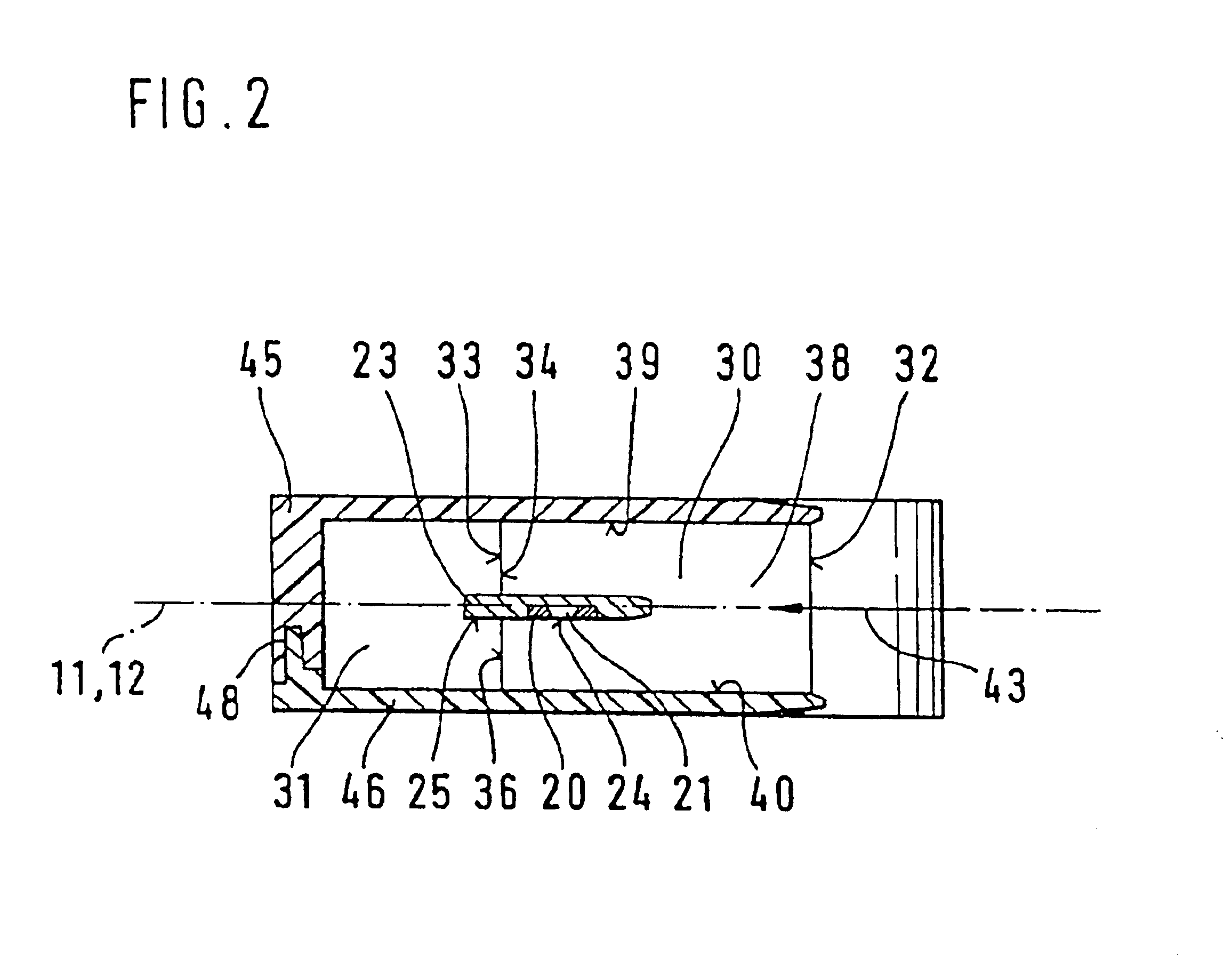
The device according to the invention for measuring the mass of a flowing medium has the advantage over the prior art that in mass production, devices with a properly manufactured housing can be produced so that only extremely slight variations in the measurement precision occur. It is also particularly advantageous that by means of the embodiment, according to the invention, of the walls of the measurement conduit, an acceleration of the flow in the measurement conduit can furthermore be maintained, which leads in a known manner to a stabilization of the flow of the medium in the measurement conduit, particularly at the inlet.Advantageous improvements and updates of the device disclosed are possible by means of the measures taken.An inclined embodiment of an edge face of the deflection it conduit is particularly advantageous, with which it is possible to further simplify the manufacturing of the measurement conduit and the deflection conduit, wherein a further improvement of the measurement result also occurs.Furthermore, a flow connection to the external flow in the intake line is provided in the deflection conduit in the form of an opening, by means of which possibly existing residual interferences of a pressure wave in the deflection conduit can be completely eliminated so that a further improvement of the measurement result can be achieved. Furthermore, the device has a considerably reduced measurement signal noise, which can be produced by means of turbulences that occur in the measurement conduit.Exemplary embodiments of the invention are shown in simplified form in the drawings and will be explained in more detail in the description that follows.FIG. 1, in a partially sectional depiction, shows a side view of the device according to a first exemplary embodiment according to the invention,FIG. 2 is a section through the device along a line II--II in FIG. 1,FIG. 3, in a partially sectional depiction, shows a side view of the device according to a second exemplary embodiment according to the invention.

Problems solved by technology

In the manufacturing, it has turned out that due to the increasing wall thickness, varying cooling speeds and accumulations of material occur, which can in particular lead to hollows in the side faces of the measurement conduit.

Method used


Image

  • Device for measuring the mass of a flowing medium in an intake tube
  • Device for measuring the mass of a flowing medium in an intake tube
  • Device for measuring the mass of a flowing medium in an intake tube

Examples


Embodiment Construction

In a partially sectional depiction, FIG. 1 shows a side view of a device labeled 1, which is used to measure the mass of a flowing medium, in particular the intake air mass of internal combustion engines. The internal combustion engine can be a mixture compressing engine with externally supplied ignition, or it can also be an air compressing, self-igniting engine. The device 1 has, for example, a narrow, rod-like, block-shaped form that extends longitudinally in the electrical direction of the plug axis 10, and is inserted into an opening let into a wall 8 of an intake line 9, for example 90 that it can be plugged in. The device 1 is sealed by means of a sealing ring 3 to an outside electrical source in the wall 8, and is connected to the wall, for example by means of a screw connection that is not shown in detail. The cross-hatched wall 8 is part of the intake line 9 that is embodied for example as cylindrical, through which the internal combustion engine can aspirate air from the ...


PUM


Abstract

A device for measuring the mass of a flowing medium with a temperature-dependent measurement element has a measurement conduit whose faces, which extend perpendicular to a surface fixed by the measurement element, are inclined and approach each other in the flow direction of the medium in the measurement conduit. The invention is provided for measuring the mass of a flowing medium to measure the intake air mass of internal combustion engines.

Description

PRIOR ARTThe invention is based on a device for measuring the mass of a flowing medium. A device has already been disclosed (DE-PS 44 07 209), which has a temperature-dependent measurement element that is accommodated in a measurement conduit that extends in a straight line. The measurement conduit extends in the device from an inlet to an outlet, which is adjoined by an S-shaped deflection conduit. The flowing medium flows from outside into the measurement conduit and then into the deflection conduit, where it flows out again from an outlet opening. The measurement conduit has a rectangular flow cross section, wherein two side faces oriented toward the platelet-shaped measurement element are embodied extending obliquely so that a tapering of the measurement conduit is produced in the flow direction of the medium in the measurement conduit. A top face of the measurement conduit, which extends lateral to the side faces and from which the measurement element protrudes, and a bottom fa...

Claims


Application Information

Patent Timeline
Patent Type & Authority Patents(United States)
IPC IPC(8): G01F1/684G01F1/68
CPCG01F1/6842
Inventor MULLER, WOLFGANGREYMANN, KLAUSKONZELMANN, UWE
Owner ROBERT BOSCH GMBH
Learn More