Lower limb function training device

a training device and lower limb technology, applied in the field of lower limb function training devices, can solve the problems of difficulty in performing passive exercises at one's convenience, many times of suitable exercise not achieving the expected improvement, and the disabled person who does not perform passive exercises

Inactive Publication Date: 2004-08-24
TAKIZAWA SHIGEO +1
View PDF5 Cites 40 Cited by
  • Summary
  • Abstract
  • Description
  • Claims
  • Application Information

AI Technical Summary

Problems solved by technology

However, it is difficult to perform passive exercises at one' convenience due to human problems.
Also in the cases that a director or caregiver are not close by, the disabled person who does not keep the caregivers instruction of the exercise repetitions and exceeds the equivalent range of the suited exercise by many times will not achieve the expected improvement.
Although, muscular-strength reinforcement became the purpose of training to the disabled person with whom the improvement progressed, load is not applied at the time of exercises and it was not able to be used for muscular-strength reinforcement.

Method used


Image

  • Lower limb function training device
  • Lower limb function training device
  • Lower limb function training device

Examples


first embodiment

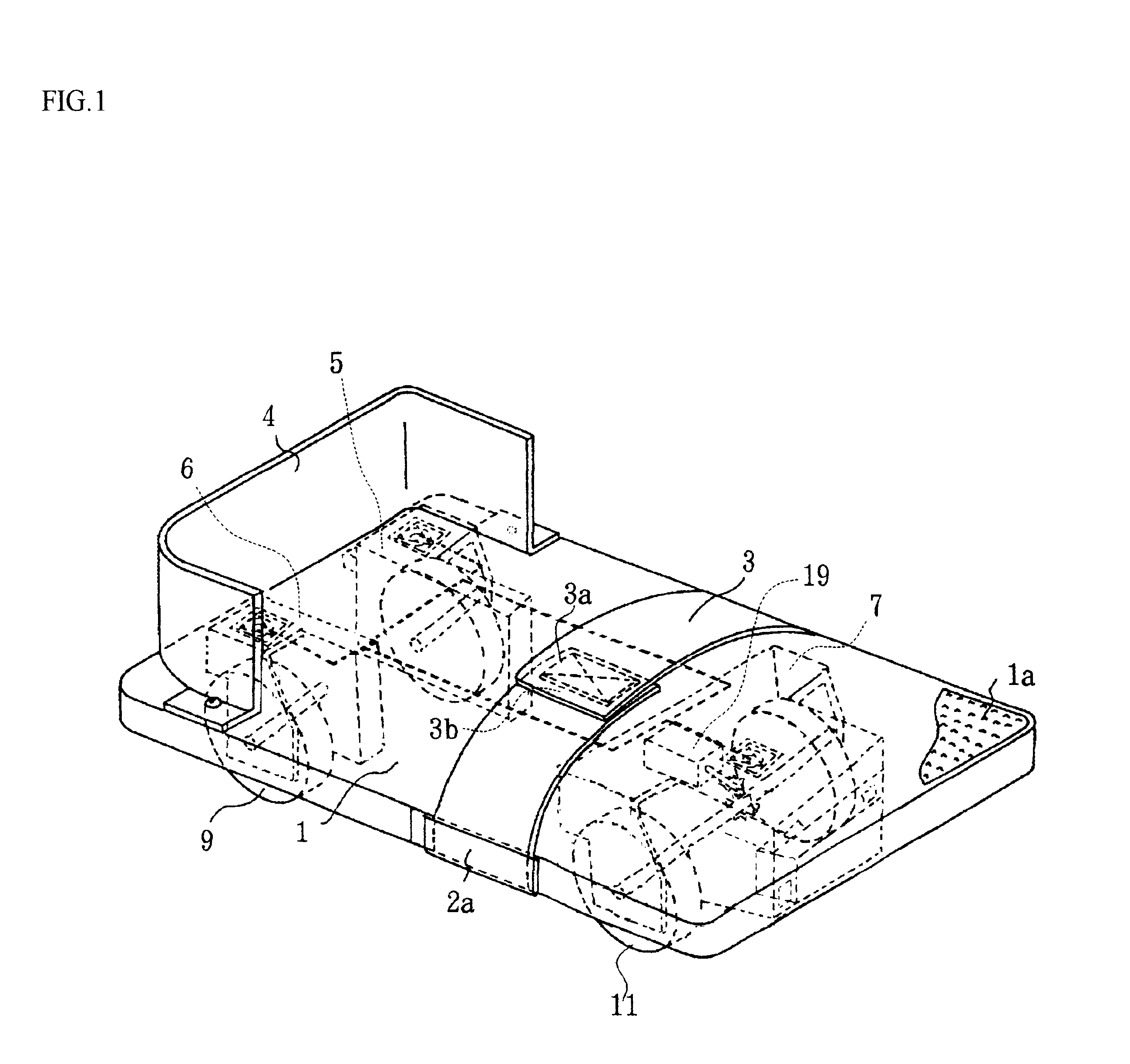
I explain a lower limb function training device in this invention by using FIG. 1 and FIG. 8.

FIG. 1 is a perspective view of a lower limb function training device of the first embodiment.

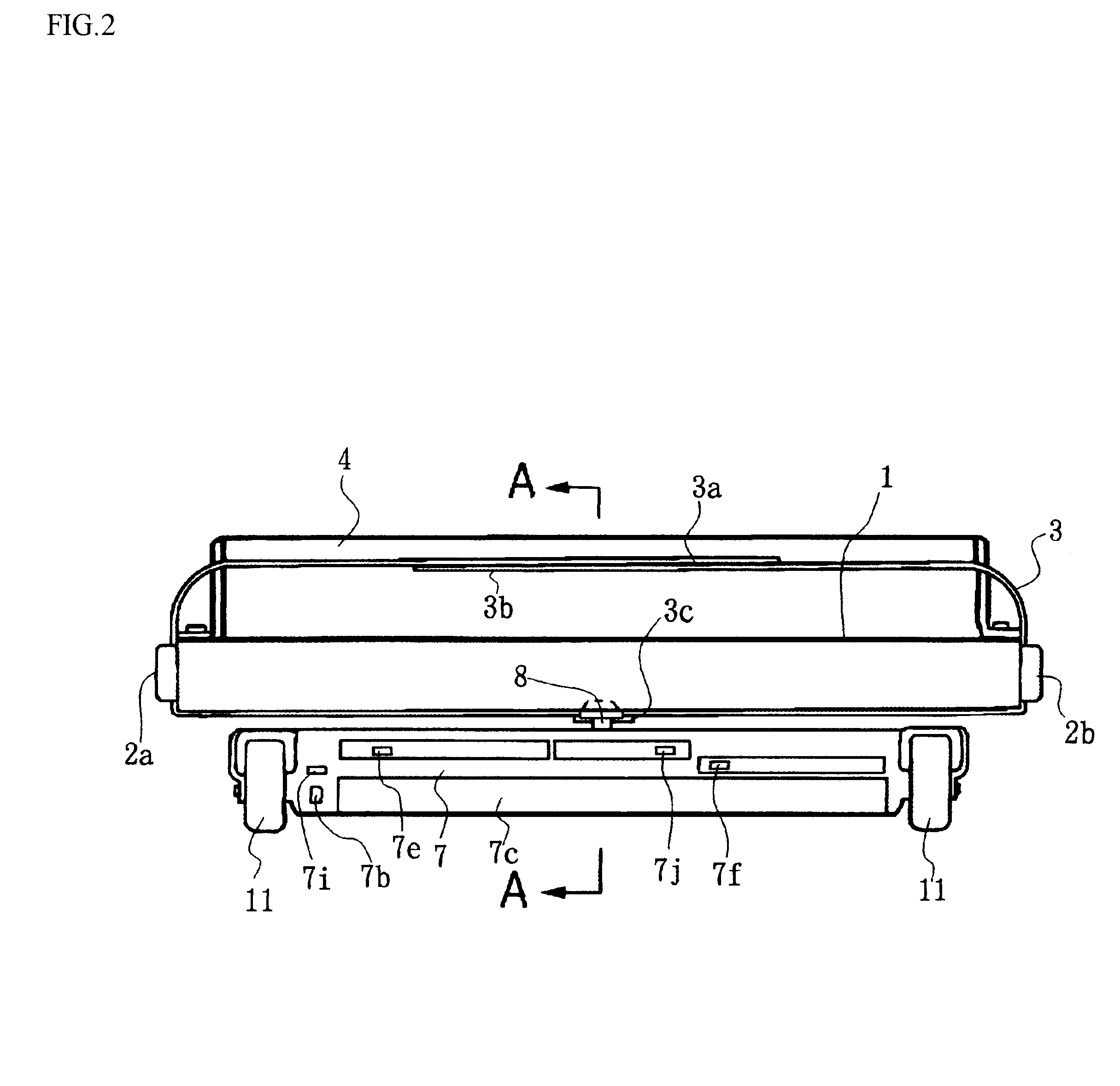
FIG. 2 is a front view of FIG. 1.

FIG. 3 is a rear view of FIG. 1.

FIG. 4 is a A--A cross section view of FIG. 2.

FIG. 5 is a side view while using, which sets and fixes the two legs.

FIG. 6 is a side view showing the state of performing Plantar Flexion exercise.

FIG. 7 is a control circuit diagram.

FIG. 8 is a flowchart in case, which the connection between a wheel and a motor are cut.

Furthermore, the drawing of a rear wheel support parts of a right and left part is omitted in FIG. 2.

Also, the drawing of the front wheel support parts is omitted in FIG. 3.

A foot rest (1) is formed with wood in midair with a plane abbreviation rectangular (or embracing necessity plastic etc.).

The foot rest (1) is having an area of sufficient width that can put both feet (51a, 51b) (for example, the size of the side of abou...

second embodiment

The second embodiment consists of a foot rest (1) and a foot rest cart (22) as a measuring instrument, and the similar functions to the first embodiment are realized by combining a foot rest (1) and a foot rest cart (22).

Same as the first embodiment, both a heel support part (4) and setting band (3) assemble a foot rest (1) of this embodiment.

Several proper pieces of wheels (21) that may move toward the right and left freely assemble an undersurface of a foot rest (1).

The lower limb function training device needs to restrict the movement in the right-and-left direction in order to detect the movement in a cross direction and to use.

However, same as the first embodiment, the progression of an exercise tends to deflect the foot (51a) with disability because of the strength of another healthy foot (51b) without any disability is strong due to setting both a foot (51a) with disability and another healthy foot (51b) without any disability.

In this case, it becomes a corrective exercise in...

third embodiment

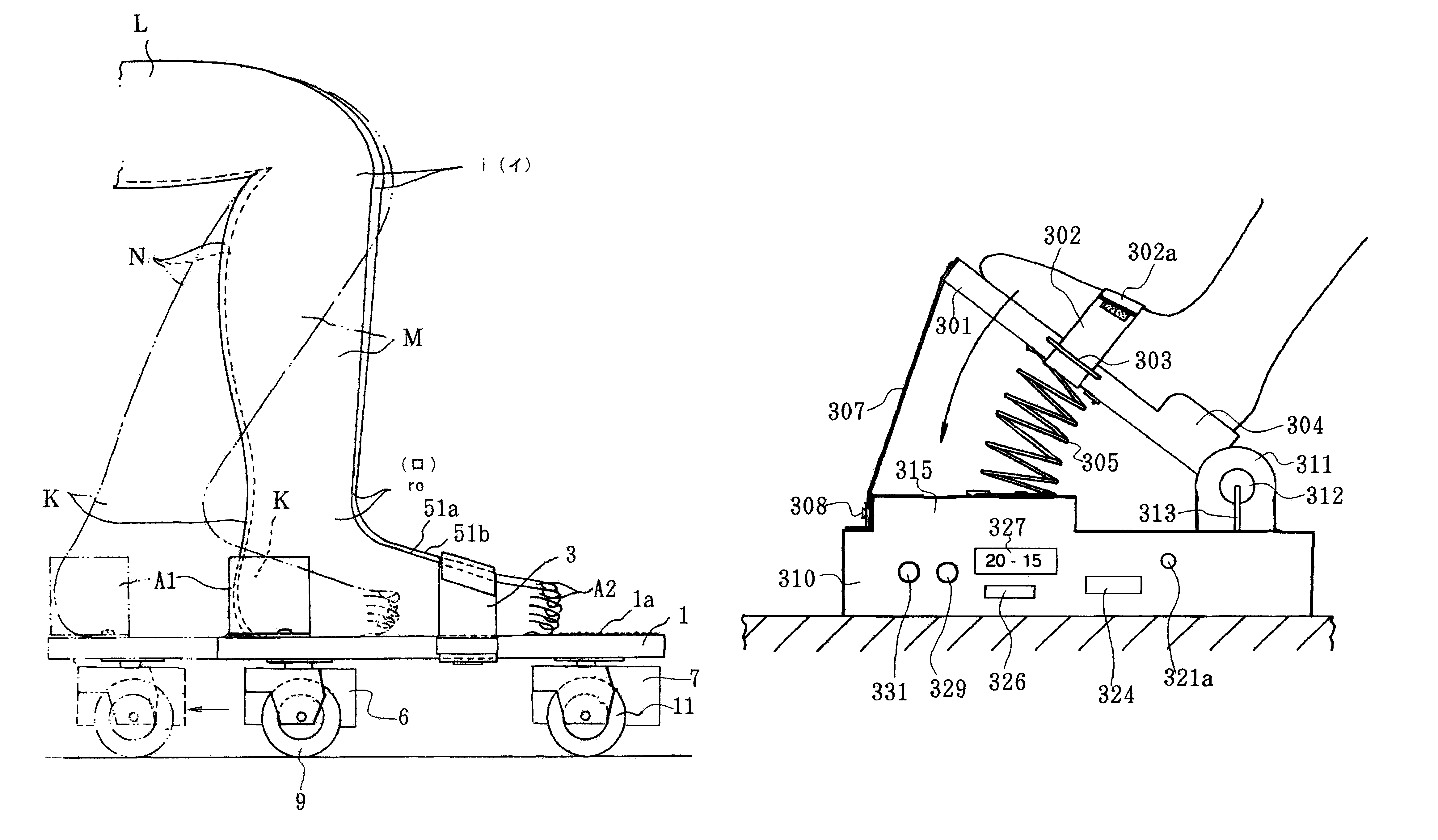
Next, I explain the third embodiment by using FIG. 14 and FIG. 17.

FIG. 14 is a side view of a lower limb function training device of the third embodiment.

FIG. 15 is a perspective view of FIG. 14.

FIG. 16 is a side view while in use, which sets and fixes the two legs.

FIG. 17 is a side view of the modification of the third embodiment,

(a) is a view of the first modification,

(b) is a view of the 2nd modification.

A foot rest (301) is formed of plastic (or can necessarily be made of wood, etc.) and empty inside with a plane similar to a rectangle.

The foot rest (301) has an area of sufficient width that can set both feet shown as FIG. 16 (for example, the size of the side about 20 cm and about 25 cm, length).

Therefore, a disabled person can set both a foot with a disability, which has hemiparesis of lower extremities of a nerve, decline of the lower extremities muscular strength that originates from a plasmotomy of Achilles' tendon of any lower extremity, a disability in range of motion, et...


PUM


Abstract

A lower limb function training device which the patient oneself can use safely with no sense of fear, which is used to prevent or improve a drop foot contracture or to expand the excursion of a joint while preventing the patient from using it over an appropriate amount of exercise to the utmost, which allows the patient to select the type of exercise, and which enables measurement of state of the body.The device is provided with a contact sensor, a foot rest on which the feet of the patient rest and selectively moves back and forth or rocks vertically, a movement counter for counting the back-and-forth movements or vertical rockings of the foot rest, and a brake device for braking the back-and-forth movement or vertical rocking of the foot rest when the count reaches a preset value.

Description

This invention is related to a lower limb function training device which makes the patient feel safe to use and is intended to prevent and / or improve the contracture of equines and also to expand the joints' range of motion.BACKGROUND TECHNOLOGYIn the case of disorders where someone has a disability as a result of hemiparesis after apoplexy, a decline of muscular strength of the lower extremities is caused by the rupture of the Achilles' tendon and / or disabilities of the range of motion in the joint of a leg or knee originating in a bone fracture of the lower extremities and other conditions if left untreated, an ankle or knee becomes a contracture and chronic disabilities of the lower extremities have been originated.Therefore, these functional disorders become the training or exercise for the needed recovery.Also, there are the judgment standards, so-called due to the strength of muscular strength developed in 5 stages depending on the exercise corresponding to the muscular streng...

Claims


Application Information

Patent Timeline
Patent Type & Authority Patents(United States)
IPC IPC(8): A61H1/02A63B23/04A63B23/08A63B22/00A63B22/20A63B21/005A63B24/00
CPCA61H1/0259A63B21/023A63B23/03525A63B23/03541A63B23/0417A63B23/0429A63B23/085A63B22/203A63B21/0058A63B2220/17A63B2225/30
Inventor TAKIZAWA, SHIGEOTAKIZAWA, KYOKO
Owner TAKIZAWA SHIGEO
Why Eureka
Try Eureka