Two-dimensional scale structures and method usable in an absolute position transducer

a transducer and two-dimensional scale technology, applied in the direction of optical radiation measurement, instruments, spectrophotometry/monochromators, etc., can solve the problems of inability to adapt or combine the structure of such absolute position encoders that are fundamentally 1-dimensional, the grating scale and readhead disclosed in the 225 patent are not adaptable to provide absolute position measurement, and the "information storage" structure of such 2d bar code systems is generally not well suited to act as

Inactive Publication Date: 2004-08-24
MITUTOYO CORP
View PDF11 Cites 78 Cited by
  • Summary
  • Abstract
  • Description
  • Claims
  • Application Information

AI Technical Summary

Benefits of technology

In various exemplary embodiments, each non-periodic code portion includes a predetermined portion that has an extent along each of the two dimensions. In each dimension, the predetermined portion may be a single element or space having predetermined characteristics, or may be a predetermined pattern of elements. This predetermined portion allows the readhead signals arising from the code portions of the scale to be rapidly located and / or distinguished from the readhead signals arising from other portions of the scale.

Problems solved by technology

However, the structures of such absolute position encoders that are fundamentally 1-dimensional are generally not adaptable or combinable to provide a high resolution and high accuracy absolute position measurement at an arbitrary position in a two-dimensional plane.
However, the grating scale and readhead disclosed in the 225 patent are not adaptable to provide absolute position measurement.
However, the "information storage" structures of such 2D bar code systems are generally not well suited to act as a 2D scale for high-resolution absolute position determinations.
Furthermore, it is not clear how to array such codes into a continuous 2D scale and reliably discriminate between adjacent codes.
The inventors of this invention have determined that ID absolute position measurement systems and 2D grating incremental measurement systems are generally difficult, costly, or impossible to adapt for use as high-resolution 2D absolute measurement systems.
Furthermore, the patterns of various 2D bar code configurations are generally not well suited to act as patterns for 2D scales for high-resolution absolute position determination.
Such bar code patterns are especially poorly suited for providing high resolution position measurements at high speed.
Such comparisons are generally too time consuming for tracking the motion of such patterns relative to a detector with both the high resolution and high speed generally desired for position measurement and motion control applications.
Furthermore, when multiple complex patterns are arrayed adjacent to each other in a 2D pattern to form a continuous 2D scale, discrimination between the various individual patterns adds further signal processing complexity and further increases the difficulty of determining the position of such patterns with both high resolution and high speed.
Moreover, generating such patterns over an extended two-dimensional area that are unique within that area while at the same time aligning these patterns with an underlying continuous periodic grid in order to provide an accurate and high-resolution absolute measurement scale is technically difficult and / or costly.
Attempting to circumvent the foregoing problems by reducing the spatial resolution and / or the distribution of such patterns will generally degrade the ability to determine the positions of these patterns with high resolution, which generally depends on the spatial frequencies or "information density", that is, the "density of transitions" present in a position measurement scale.

Method used


Image

  • Two-dimensional scale structures and method usable in an absolute position transducer
  • Two-dimensional scale structures and method usable in an absolute position transducer
  • Two-dimensional scale structures and method usable in an absolute position transducer

Examples


Embodiment Construction

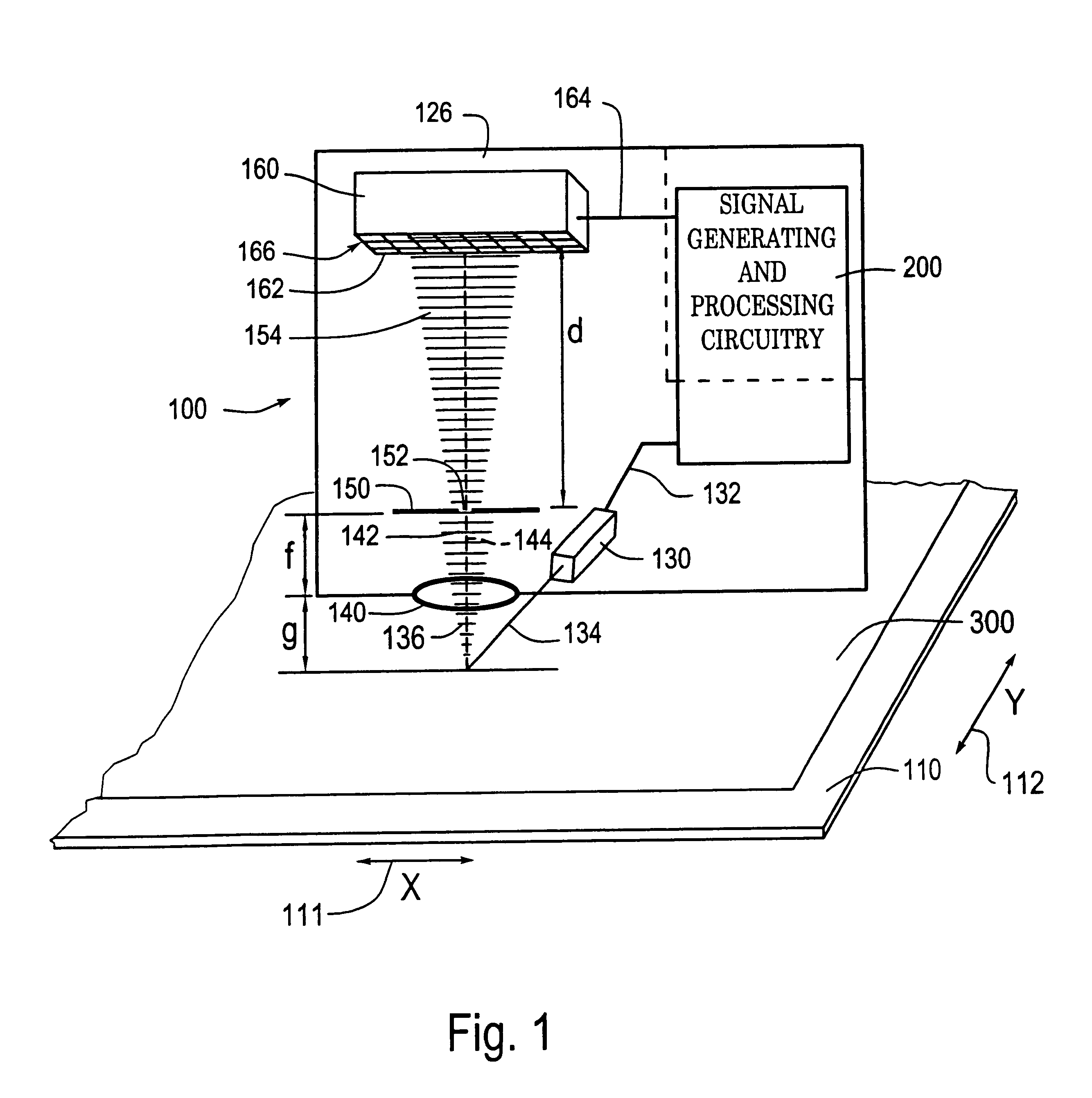
FIG. 1 is a block diagram of a 2D optical absolute position encoder 100 usable with a 2D integrated scale pattern according to this invention to generate a 2D absolute position measurement. The 2D optical absolute position encoder 100 shown in FIG. 1 includes a readhead 126, signal generating and processing circuitry 200 and a 2D scale 110. The 2D scale 110 includes a 2D integrated scale pattern 300. In FIG. 1, the components of the readhead 126, and their relation to the 2D scale 110 and the 2D integrated scale pattern 300, are shown schematically in a layout that generally corresponds to an exemplary physical configuration, as further described below.

In particular, the scale 110 is positioned adjacent to an illuminating and receiving end of the readhead 126, such that when the 2D scale 110 is illuminated by light emitted from that end of the readhead 126 by a light source 130, the emitted light is selectively reflected back by the 2D integrated scale pattern 300 on the 2D scale 11...


PUM

PropertyMeasurementUnit
focal lengthaaaaaaaaaa
diameteraaaaaaaaaa

Abstract

An absolute 2D position-sensing device is usable to measure the relative position of two elements. A 2D absolute scale includes an integrated 2D absolute scale pattern extending over the 2D scale area along each measuring axis of the scale. The integrated 2D absolute scale pattern includes a plurality of periodic portions interleaved with a plurality of non-periodic portions along each axis. Each periodic portion includes a plurality of periodically-placed scale elements. Each non-periodic portion includes a plurality of code elements indicative of an absolute measurement value. The code elements may have a length that is narrower along each measuring axis is than the length of the periodic scale elements along each measuring axis. The offset of the periodically-placed elements relative to a readhead of the device is combined with the absolute measurement value to determine an absolute position.

Description

1. Field of InventionThis invention relates to an absolute position optical displacement-sensing device that senses absolute positions in two dimensions.2. Description of Related ArtAbsolute position encoders use a scale structure that allows the position of a readhead relative to a scale to be determined without requiring any reference to a given starting point along the scale. A variety of 1-dimensional (1D) absolute position encoders are known that use multiple information patterns extending in parallel along a 1-dimensional scale. Also, 1D and 2-dimensional (2D) codes have been used as a means to identify positions along ID scales. However, the structures of such absolute position encoders that are fundamentally 1-dimensional are generally not adaptable or combinable to provide a high resolution and high accuracy absolute position measurement at an arbitrary position in a two-dimensional plane.A two-dimensional (2D) incremental (non-absolute) position encoder providing high reso...

Claims


Application Information

Patent Timeline
Patent Type & Authority Patents(United States)
IPC IPC(8): G01D5/347G01D5/26G01B11/00G01D5/249G01D5/30G01D5/36
CPCG01D5/34707G01D5/34776G01D5/34792G01D2205/90
Inventor NAHUM, MICHAELJONES, BENJAMIN K.RENALDS, PATRICK A.ZWILLING, AVRON M.ATHERTON, KIM W.
Owner MITUTOYO CORP
Why Eureka
Try Eureka