Janitorial service sink eyewash

a technology for cleaning personnel and eyewash, which is applied in the direction of drawing-off water installations, physical therapy, construction, etc., can solve the problems of chemicals splashing into the face, eyes or body of cleaning personnel, and the apparatus is not normally attached

Inactive Publication Date: 2004-08-31
SPEAKMAN
View PDF31 Cites 38 Cited by
  • Summary
  • Abstract
  • Description
  • Claims
  • Application Information

AI Technical Summary

Benefits of technology

are achieved by arranging a washing apparatus on the end of a flexible hose so it can be grabbed by someone affected by exposure to caustic or hazardous substances. This enables one to instinctively draw the washing apparatus from its holder and towards oneself to douse the affected area of the body.
In a typical service sink area, the sink extends a good distance from the wall of the janitorial closet thereby increasing the difficulty of reaching a fixed washing apparatus located on or near the back wall of the closet. To overcome this problem, in a preferred embodiment of the invention, the eye washing apparatus is mounted on a bracket that extends away from the wall toward the front of the service sink.
To insure consistent availability of water flow to the emergency-washing device, one end of the flexible tubing is attached to the stop cock on the faucet arranged over the service sink. A faucet preferred for use in this invention is a service sink faucet sold by the assignee of this application, Speakman Company of Wilmington, Del. as Model Number SC-5811. Stop cocks in the bottom of the faucet provide access to a cold water supply at all times, thereby providing an ideal arrangement for provision of water for emergency washing.

Problems solved by technology

However, to adjust flow through the emergency eyewash, the user, who is usually blinded by contaminants, must rotate the eyewash spray heads, either horizontally or vertically into a certain position before cleansing water will flow.
However, this apparatus is not normally affixed to the faucet and this must be found and attached to the faucet before it will operate as an eyewash.
It thus becomes somewhat impractical in an emergency.
Cleaning personnel working in and around the sink are often exposed to caustic cleaning chemicals used in their work.
The danger exists that such chemicals can splash into the face, eyes or body of cleaning personnel.
In a typical service sink area, the sink extends a good distance from the wall of the janitorial closet thereby increasing the difficulty of reaching a fixed washing apparatus located on or near the back wall of the closet.

Method used


Image

  • Janitorial service sink eyewash
  • Janitorial service sink eyewash

Examples


Embodiment Construction

The following detailed description of the invention refers to the accompanying drawings. The same reference numbers in different drawings identify the same or similar elements. Also, the following detailed description does not limit the invention. Instead, the scope of the invention is defined by the appended claims and equivalents thereof.

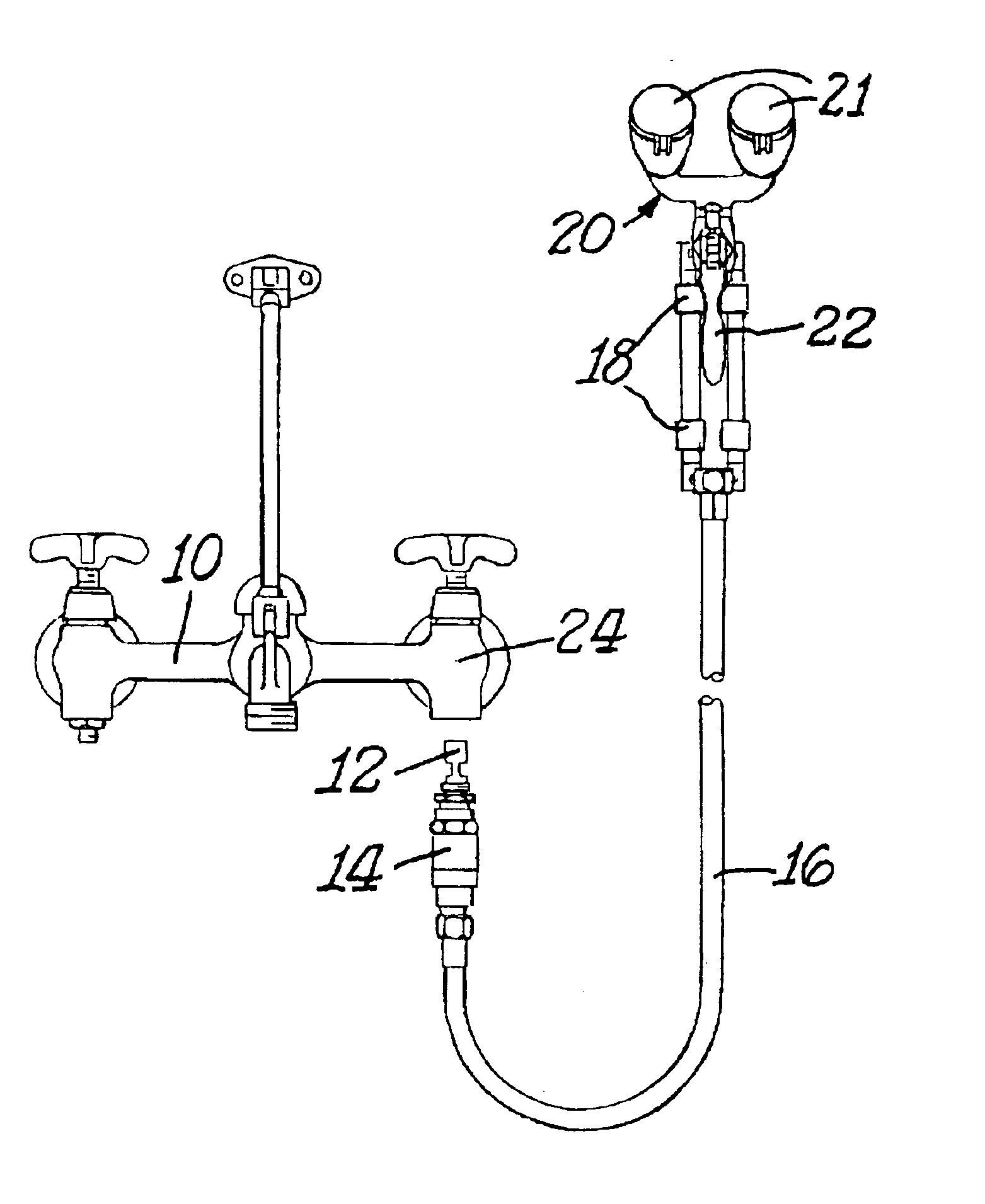
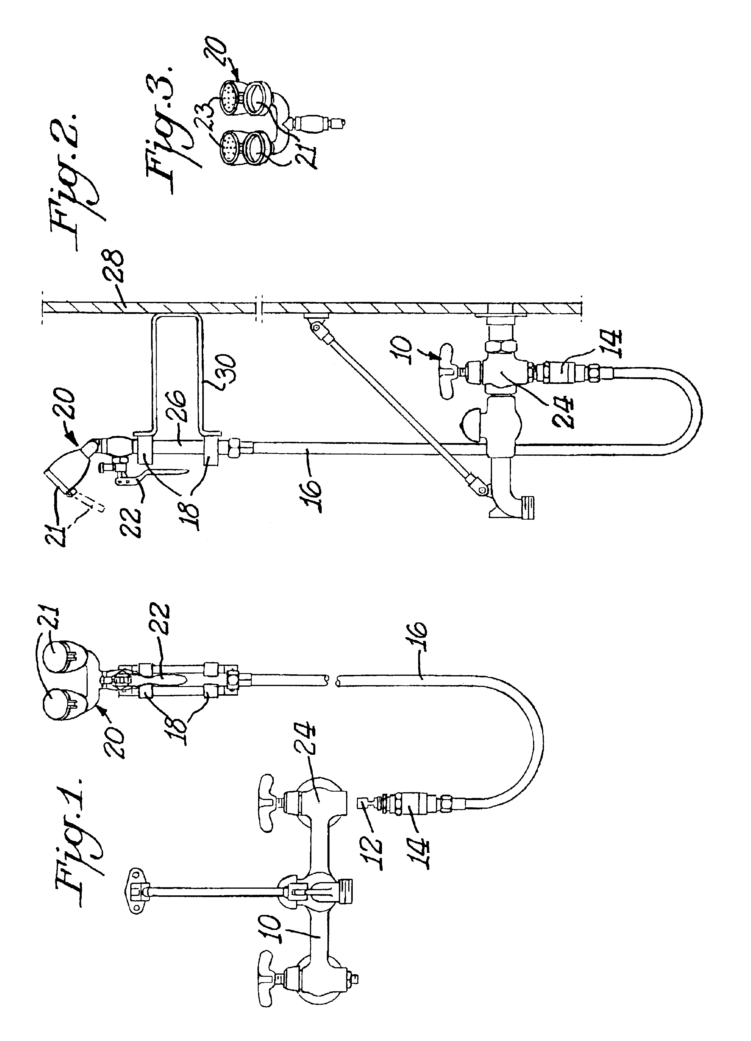
Turning now to the drawings and specifically FIGS. 1 and 2, service sink faucet 10, is typically arranged above a service sink in a janitorial closet. The faucet 10 has a cold water valve 24, wherein stop spindle and retaining nut are replaced with a vacuum breaker 14 with a check valve 12. The eyewash unit 20 is coupled to the cold water cock 24 by flexible tubing 16.

FIG. 2 demonstrates both the service sink fitting 10 and eyewash unit 20 as mounted on a wall 28. The eyewash unit 20 is releaseably mounted by the means of a wall mount bracket 30, equipped with retainer arms 18. The length of the bracket 30 enables the eyewash to be positioned clos...


PUM


Abstract

An emergency washing unit flexibly connected to a service sink faucet, wherein water flow through the unit can be initiated by simply grabbing the unit and squeezing the handle operator on the unit. The unit can be directed anywhere onto the person using it because of its connection to a water supply via a flexible hose. The unit may be mounted on brackets that hold it in a position closer to the user. A vacuum breaker can be used to prevent possible contamination caused by unwanted flow back of used water through the washing unit into the faucet.

Description

A. Field of the InventionThis invention relates generally to a service sink system which can be rapidly changed into an apparatus for washing harmful and / or hazardous substances from the body. The system is also designed to prevent contamination of the potable water system by unwanted back flow of non-potable water through the emergency washing apparatus. The service sink environment of this invention is typified by a low sink used by cleaning personnel to wash mops, fill cleaning buckets, and the like. Such sinks usually have faucets arranged above the sink that are a source of hot and cold water used by cleaning personnel. The emergency washing apparatus of this invention is connected to such a faucet.B. Description of the Related ArtEmergency washing devices are generally known in the art for emergency flushing of hazardous and / or irritating substances from human skin and / or eyes. Some typical arrangements for such devices are described below. None are adapted for use with a serv...

Claims


Application Information

Patent Timeline
Patent Type & Authority Patents(United States)
IPC IPC(8): A61H35/00A61H35/02
CPCA61H35/02
Inventor NOVAK, CHARLES J.FLEITZ, JAMES F.STIEBRIS, IMANTS A.
Owner SPEAKMAN
Why Eureka
Try Eureka