Hole puncher and reinforcer

a technology of reinforcement and punching hole, which is applied in the field of combination punching and reinforcement, can solve the problems of affecting the structure of paper fastened in the area, the task of reinforcing the punching hole in the hundreds, and even thousands of sheets of paper, and the tradition of manual operation

Inactive Publication Date: 2004-09-14
HUI JOHN
View PDF22 Cites 52 Cited by
  • Summary
  • Abstract
  • Description
  • Claims
  • Application Information

AI Technical Summary

Problems solved by technology

A problem that has persisted through the years is that considerable stress is often applied to the structure of papers fastened in files in the area immediately surrounding the punched holes.
The principal problem with this prior arrangement is that it has historically been performed manually.
The task of reinforcing punched holes in the hundreds, and even thousands, of sheets papers that are secured in files by the manual application of such reinforcing rings is often so labor intensive as to be impractical.
These tape reinforcement devices also have, to a large extent, proved impractical.
The feed mechanisms for the tape often jam and the tape often adheres to parts of the punching machines as it is fed toward the location on the sheets of paper at which it is to be applied.
Another problem with systems employing adhesive tape to reinforce the areas about punched holes is that the punch mechanism must penetrate not only the paper in which the fastening apertures are to be formed, but also the tape as well.
This creates a certain gumminess in the punch mechanism that reduces the effectiveness of the punch in creating apertures.
Also a build-up of adhesive in the punch mechanism contributes to the fouling of the tape as the tape is fed into position to be pressed against the paper.
However, since the upper surface of the reinforcement rings are treated so as to be resistant to adhesive, the adhesive bond between the undersurface of the reinforcement ring directly above the lowermost reinforcement ring and the upper surface of the lowermost reinforcement ring is quite weak.
As a practical matter, however, it is likely that some of the weak bonds between rings in the stack will fail, and some of the reinforcement rings may drop off the punching tip of the die punch if the punching tip has the same diameter as the die punch shank.

Method used


Image

  • Hole puncher and reinforcer
  • Hole puncher and reinforcer
  • Hole puncher and reinforcer

Examples


Embodiment Construction

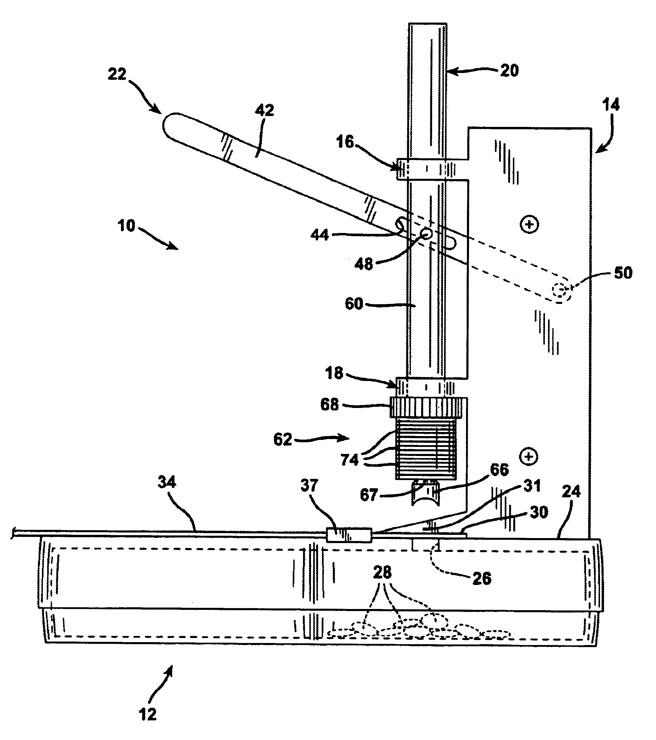
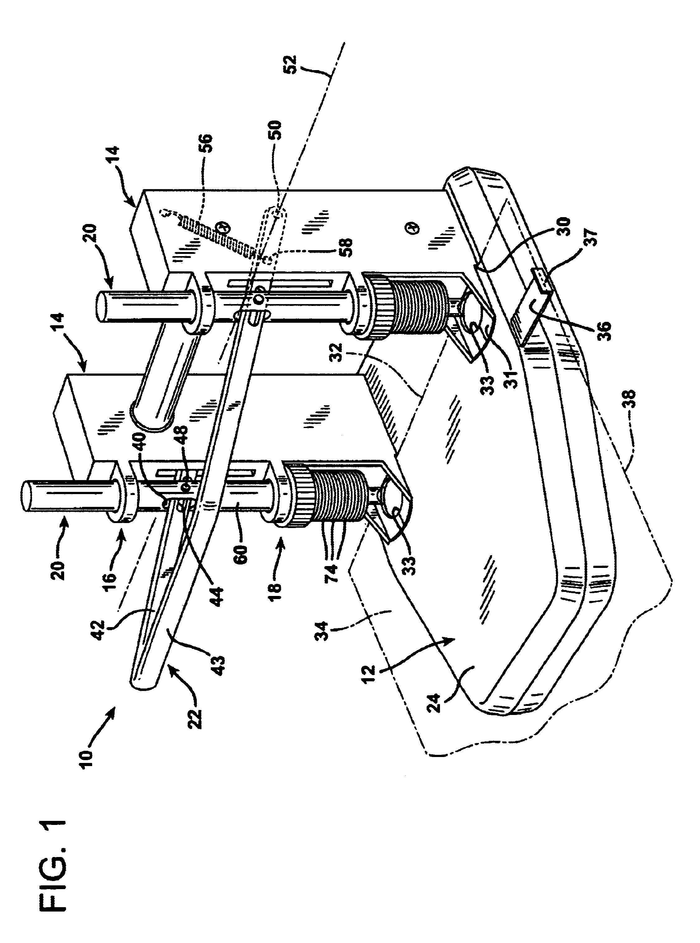
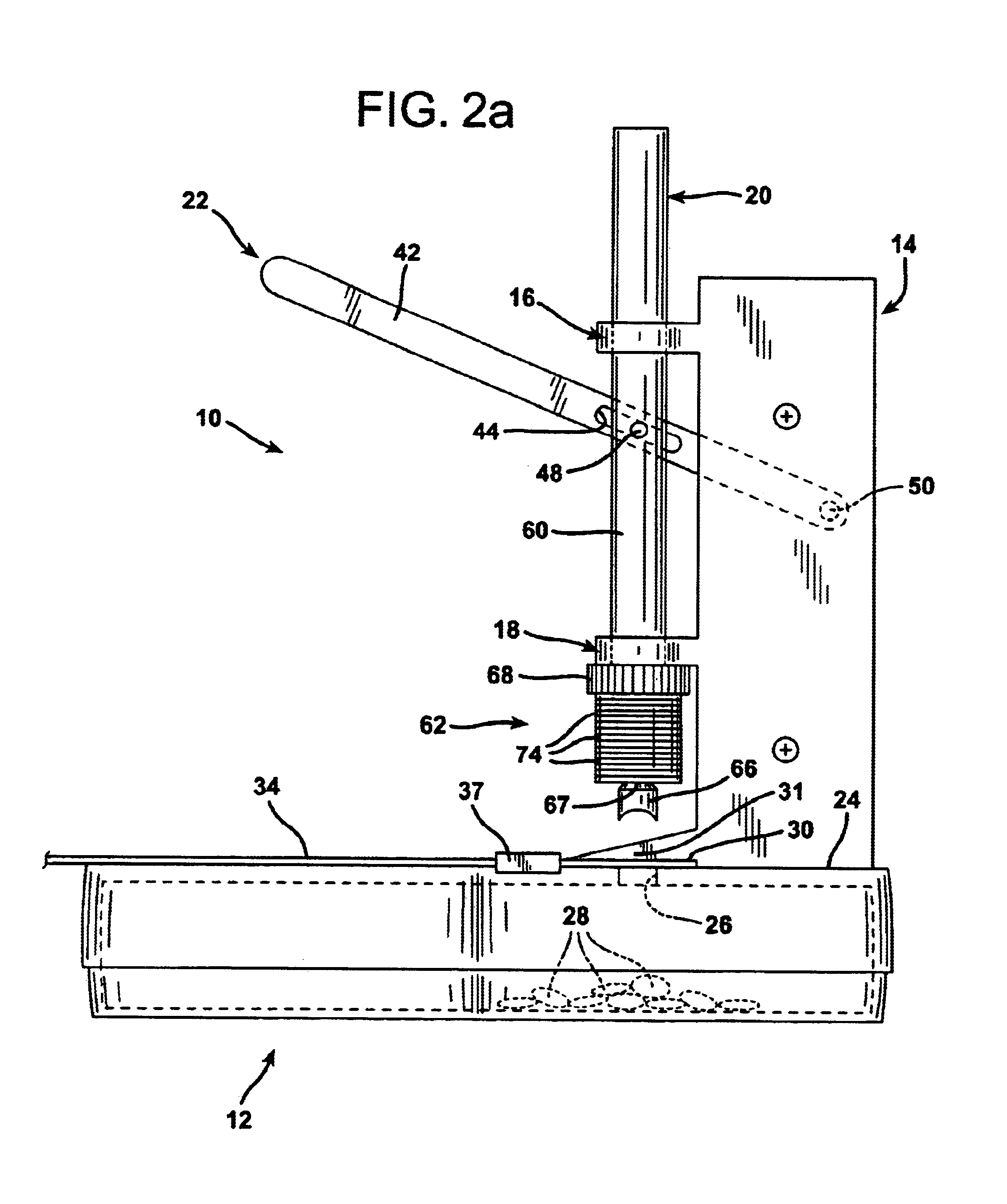
FIG. 1 illustrates a combination hole puncher and reinforcer generally at 10. The hole puncher and reinforcer 10 is a mechanical, manually operated device that has several component elements. The device 10 includes a base 12, a pair of stanchions 14 which are laterally spaced apart from each other and mounted atop the base 12, pairs of upper and lower guide loops 16 and 18, respectively, a pair of punching rams 20, and a U-shaped operating lever 22. The base 12 serves as a stabilizing support and has a flat, bright, electroplated upper deck 24. A pair of laterally spaced die-receiving openings 26 are defined through the structure of the flat, bright, electroplated upper deck 24, as illustrated in FIGS. 2a, 4, and 6. The pair of stanchions 14 project upwardly from the deck 24 in perpendicular orientation thereto and are anchored to the base 12. The interior of the base 12 below the deck 24 is hollow so as to define a cavity to receive punched chads of papers, illustrated in phantom i...


PUM

PropertyMeasurementUnit
sloping angleaaaaaaaaaa
diameteraaaaaaaaaa

Abstract

A combination hole punching and reinforcing device for punching holes in sheets of paper and other sheet materials applies flat reinforcement rings about holes formed in those sheets concurrently as the holes are formed. The device employs a die punch, which is preferably configured as a disposable item that is detachable from the lower end of the punching ram. The die punch is configured with a punching tip at its lower extremity and a shank that is preferably narrower than the punching tip. A plurality of reinforcement rings are stacked one atop each other and are carried upon a shoulder formed at the demarcation between the die punch tip and the die punch shank. A transverse pressure plate located atop the shank applies pressure to sequentially affix the lowermost reinforcement ring in the stack to a sheet of paper concurrently with the formation of an aperture through that sheet. Each reinforcement ring is formed with a pressure-sensitive adhesive on its undersurface and an upper surface treated with a silicone release coating. Therefore, once each lowermost reinforcement ring is attached about an aperture formed in a sheet of paper, the remaining reinforcement rings in the stack are lifted by the die punch and detached from the lowermost ring.

Description

1. Field of the InventionThe present invention relates to a combination hole puncher and reinforcer by means of which holes are punched in sheets of material, such as paper, and concurrently reinforced with flat, annular rings around the holes.2. Description of the Prior ArtIn offices throughout the world hole punching devices have been utilized for many years so as to punch holes in sheets of paper, and sometimes plastic sheets, to allow those sheets to be secured in files. Sheets of paper are often punched at the top with a pair of holes that allow them to be secured at the top to files using pronged fasteners. Other types of hole punchers are used to punch holes in papers and other sheets of material along the sides to allow them to be secured in ring binders.A problem that has persisted through the years is that considerable stress is often applied to the structure of papers fastened in files in the area immediately surrounding the punched holes. The papers then tear through the...

Claims


Application Information

Patent Timeline
Patent Type & Authority Patents(United States)
IPC IPC(8): B42F3/00B26D7/00B26D7/34
CPCB26D7/34B42F3/006Y10T156/1304Y10T156/1313Y10T156/1766Y10T156/1763Y10T156/1378
Inventor AONO, ISAOHUI, JOHN
Owner HUI JOHN
Why Eureka
Try Eureka