Confocal ellipsoidal mirror system for wide field of view imaging

a wide field of view, optical ellipsoidal mirror technology, applied in the direction of mirrors, spectacles/goggles, instruments, etc., can solve the problems of wide field of view imaging system, chromatic aberration, share,

Inactive Publication Date: 2004-09-14
THE UNITED STATES OF AMERICA AS REPRESENTED BY THE SECRETARY OF THE NAVY
View PDF14 Cites 17 Cited by
  • Summary
  • Abstract
  • Description
  • Claims
  • Application Information

AI Technical Summary

Problems solved by technology

Generally, wide field of view imaging systems are refractive or catadioptric, and thus suffer from chromatic aberration and are generally to heavy for applications such as space surveillance.
Wide field of view imaging systems, however, share a common problem which is field curvature.
In addition existing reflec...

Method used


Image

  • Confocal ellipsoidal mirror system for wide field of view imaging
  • Confocal ellipsoidal mirror system for wide field of view imaging
  • Confocal ellipsoidal mirror system for wide field of view imaging

Examples


Embodiment Construction

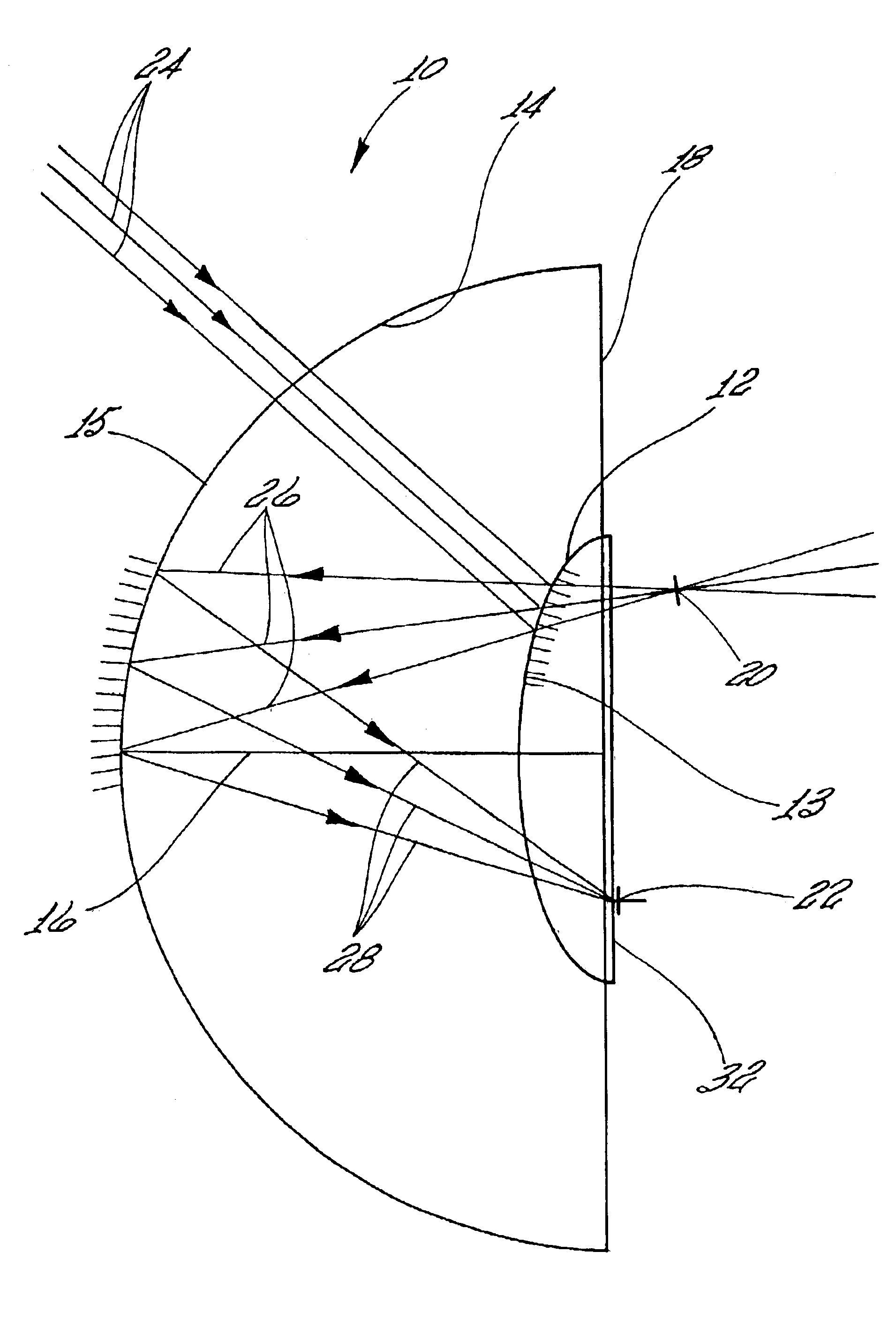
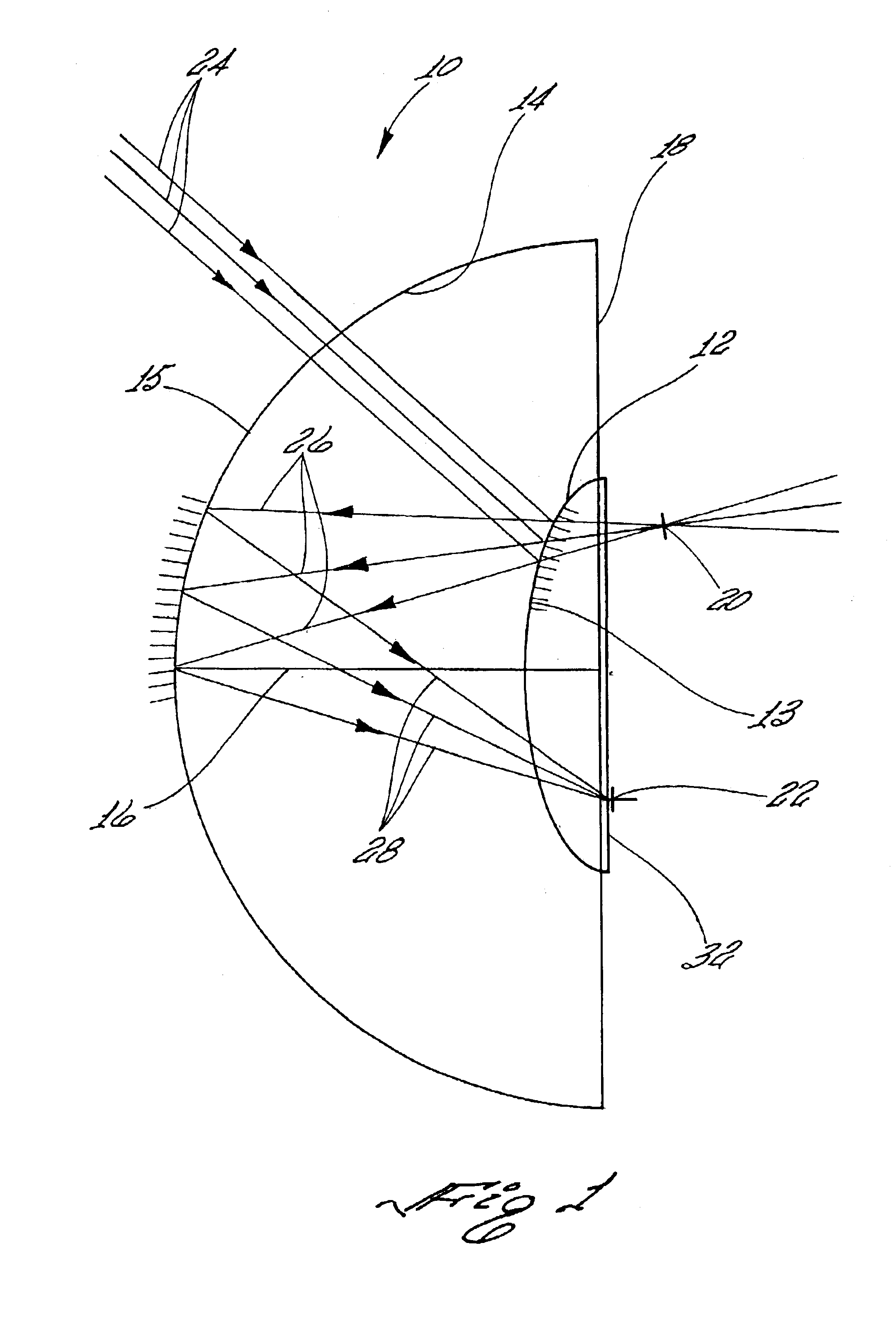
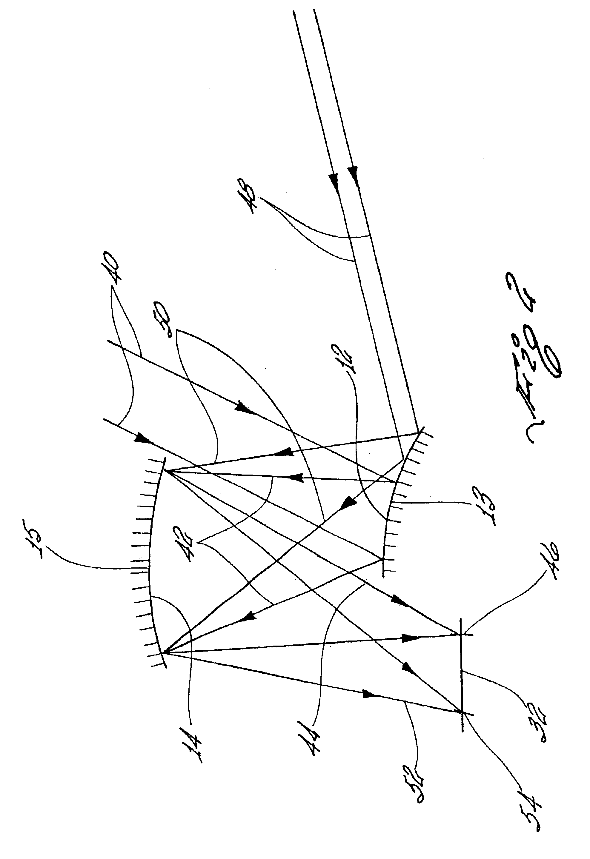
Referring to FIG. 1, there is shown an optical system, designated generally by the reference numeral 10, which is an all reflective, two mirror design capable of imaging a field of view 90.degree. in azimuth and 25.degree. to 75.degree. in elevation. The optical system 10 includes a first elliptical shaped reflective surface 12 with surface 12 being convex and a second elliptical shaped reflective surface 14 with surface 14 being concave. Surfaces 12 and 14 form oblate ellipsoids 13 and 15, respectively. Oblate ellipsoids 13 and 15 are ellipses rotated about a minor axis 16. The ellipsoids 13 and 15 share a common minor axis 16 which is the optical axis for the optical system 10.

The reflective surfaces 12 and 14 may be, for example, mirrors which reflect incoming light from a wide field of view scene or other object. Aluminum may be used for the mirror surface of each mirror and may be shaped with a diamond turning machine.

When there is a rotation about minor axis 16, the foci of th...


PUM


Abstract

An optical system having a pair of ellipsoidal shaped reflective surfaces or mirrors which receive light from an object and provide wide field view imaging for the object. The optical system directs the light onto a flat detector to a record a wide field of view image of the object on the flat detector.

Description

1. Field of the InventionThe present invention relates generally to optical systems for image viewing. More particularly, the present invention relates to an optical system which utilizes a pair of ellipsoidal reflective surfaces to provide for wide field of view imaging.2. Description of the Prior ArtCurrently, wide field of imaging optics are used for a multitude of purposes including photographic, remote sensing and space surveillance imaging. Generally, wide field of view imaging systems are refractive or catadioptric, and thus suffer from chromatic aberration and are generally to heavy for applications such as space surveillance.Reflective optics do not suffer the drawbacks of refractive optics. Wide field of view imaging systems, however, share a common problem which is field curvature. This prevents a user from having the image sensed by a flat detector such as focal plane array or photographic film. In addition existing reflective wide field of view imaging systems are compl...

Claims


Application Information

Patent Timeline
IPC IPC(8): G02B17/06G02B13/06G02B17/00
CPCG02B13/06G02B17/0615
Inventor GARCIA, DANIEL F.
Owner THE UNITED STATES OF AMERICA AS REPRESENTED BY THE SECRETARY OF THE NAVY
Why Eureka
Try Eureka