Single beam aircraft passenger seat

a passenger seat and single beam technology, applied in the field of aircraft seats, can solve the problems of increasing design and assembly costs, adding weight to the overall seat design, and increasing the required inventory of parts

Inactive Publication Date: 2004-10-05
BE AEROSPACE INCORPORATED
View PDF17 Cites 40 Cited by
  • Summary
  • Abstract
  • Description
  • Claims
  • Application Information

AI Technical Summary

Benefits of technology

The beam 18 represents a radical departure from conventional seat design, where a pair of parallel fore-and aft beams provide support to the entire seat structure. The beam 18 is oval in cross-section and downwardly curved laterally across the front of each of the seats 10A, 10B, 10C. This combination of the oval cross-section and the curve provides sufficient strength to support the entire on the leg assemblies 12 and 13, thus eliminating the need for a second beam.
Referring now to FIGS. 2, 3 and 4, seat 10A, exemplary of each of the seats 10A, 10B, 10C, has a curved, semi-rigid diaphragm support 30 carried by seat frames 14, 15 in alignment with the curved shape of the seat frames 14, 15 and mounted for movement relative to the seat frames 14, 15 between a first, upright position, FIG. 2, and a second, reclined position, FIG. 3. The diaphragm support 30 is preferably made of a controlled flex material, such as a laminated composite carbon fiber resin. This material is well-known as a lightweight, durable and relatively inert material particularly suitable for aircraft use. Other materials having similar characteristics may also be used, including various polymers, particularly including nonflammable polymers. The support 30 is molded into the desired shape using conventional carbon fiber molding and fabrication techniques, and forms a seat back 30A and a seat bottom 30B.
The above-described seat design has the effect of causing the passenger to recline by rotating the passenger about a pivot point in the area of the hips. The passenger's back moves downwardly and the legs move upwardly, maintaining the same relative body position. This provides a more comfortable recline position without the tendency of the passenger to merely slide forward on the seat bottom when the seat back is reclined.
Referring now to FIG. 6, the view demonstrates features that result from moving the arm rest pivot forwardly and the absence of the aft beam present in prior art seats. As is shown, the pivot of the arm rest 23 is now at a point directly under the elbow of the passenger, and does not extend rearwardly into the plane of the seat back. Without the requirement to provide space between adjacent seat backs for the stowed arm rest to reside, the seat back can be made wider, and the area where the arm rest pivot would normally be positioned can be made available for other uses. As shown in FIG. 6, the seat back 30A includes two concave, inwardly-dished areas 62, 63 that reside forwardly of the knee areas of the aft-seated passenger. These areas provide greater knee clearance for all passengers and particularly for taller passengers whose knees are typically within several inches of the seat back, it not actually touching. This, in combination with the above-described seat back design features that avoid aft movement of the seat back 30A when the passenger reclines the seat, provides an ergonomic design that provides greater comfort for both the forward and the aft-seated passengers.
This design illustrates further advantages obtained by maintaining the seat back in a stationary position. The video screen 72 does not move and thus does not require a mechanism to pivot the screen 72 to compensate for movement of the seat back. All of the controls on the seat back 39 are easy to see and reach by the passenger.

Problems solved by technology

These beams add weight to the overall seat design, increase required inventory of parts, increase design and assembly expense, and take up space under the seat that could otherwise be used for more foot and leg room, or stowage of carry on baggage.

Method used


Image

  • Single beam aircraft passenger seat
  • Single beam aircraft passenger seat
  • Single beam aircraft passenger seat

Examples


Embodiment Construction

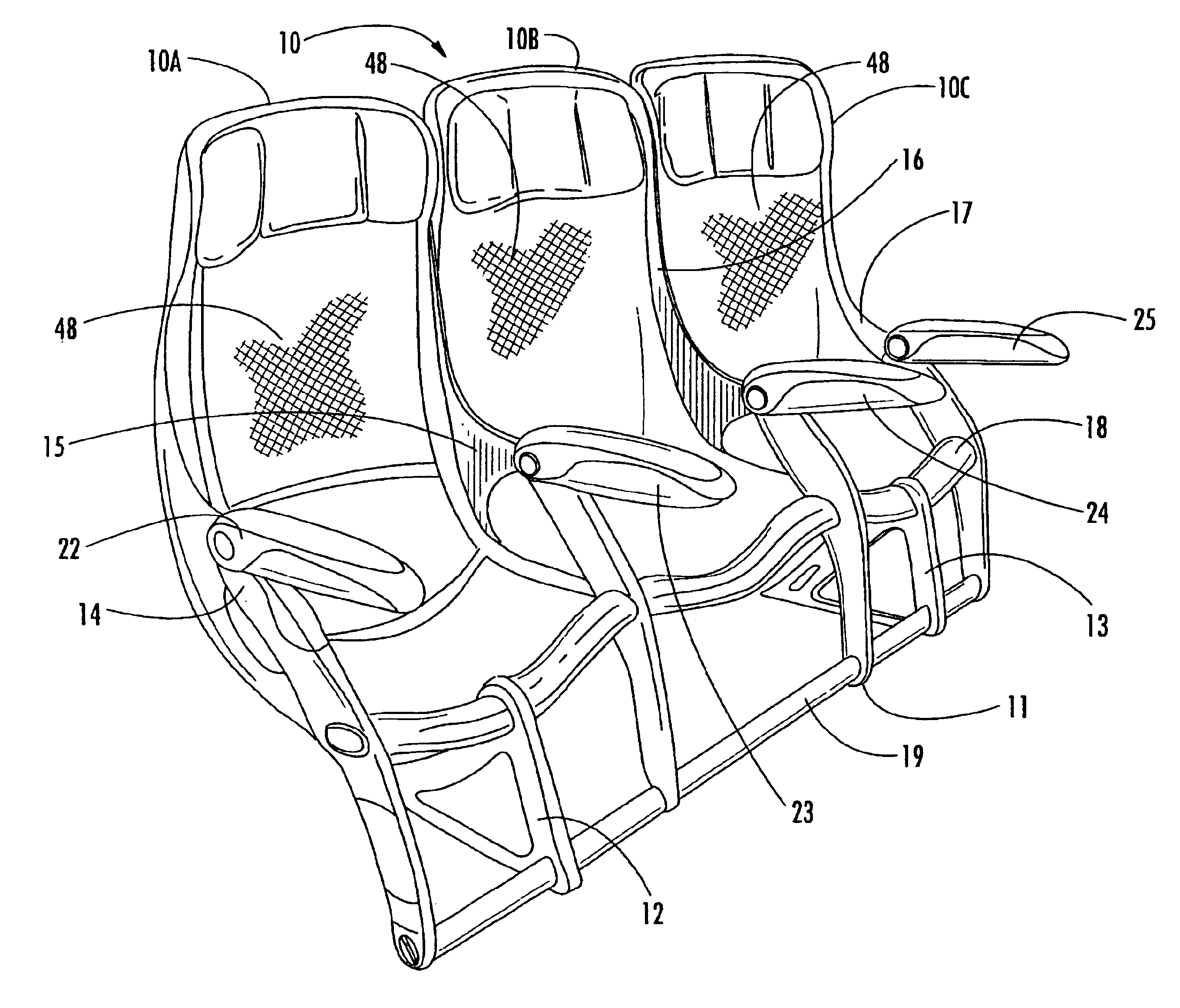
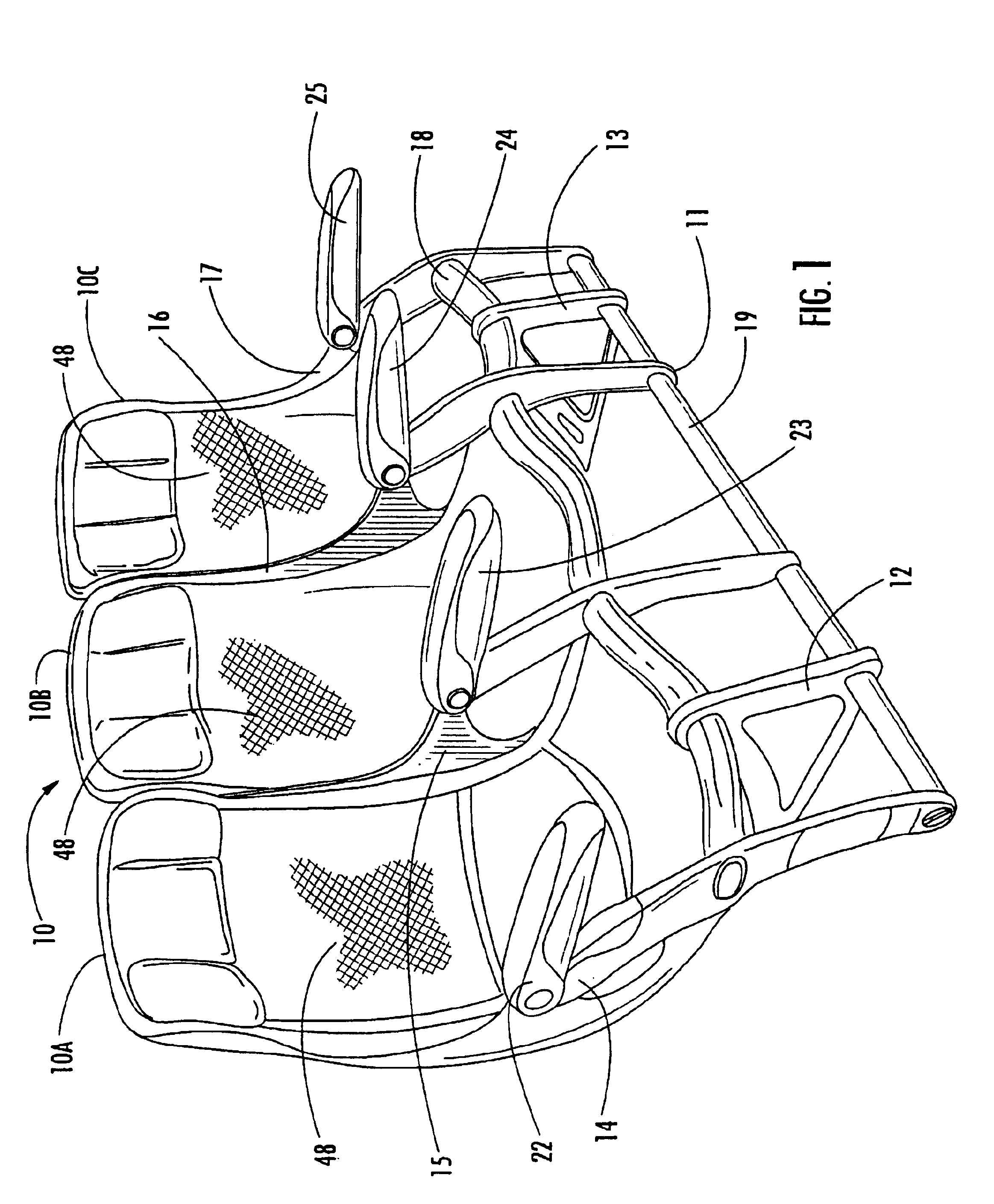
Referring now specifically to the drawings, a three-seat seat set according to the present invention is illustrated in FIG. 1 and shown generally at reference numeral 10 and comprises individual joined seats 10A, 10B, 10C that are movable from an upright to a recline position without encroaching on an aft-seated passenger. This type of seating is conventionally referred to as "coach" or "main cabin" seating as distinct from larger and more complex first class or business class seating. As will be seen below, the features of this invention are also applicable to first and business class seating. The seat set 10 includes a seat base 11. The seat base 11 includes a pair of leg assemblies 12 and 13 for being attached to a supporting surface by means of conventional track fittings such as disclosed in applicant's U.S. Pat. Nos. 4,776,533; 5,169,091 and 5,871,318. Four seat frames 14, 15, 16 and 17 are connected by single laterally-extending beam 18. A baggage guard rail 19 prevents bagga...


PUM


Abstract

A passenger seat, including at least one leg assembly having fore and aft attachment elements for attachment to a supporting surface and a single laterally-extending beam carried by the leg assembly in vertically spaced-apart relation to the fore and aft attachment elements, and first and second laterally spaced-apart seat frames positioned on respective opposite sides of the leg assembly and mounted on the beam for being supported thereby.

Description

TECHNICAL FIELD AND BACKGROUND OF THE INVENTIONThis invention relates to an aircraft seat, particularly an aircraft passenger seat, with a single seat beam. Aircraft passenger seats are typically constructed from modular components, the size, weight and construction of which are dictated by many considerations, including fuselage dimensions, aesthetic and safety considerations. Many of these requirements are imposed by law or regulation. The lower seat chassis is constructed of leg modules, while the upper seat is constructed of section assembly modules. In prior art seating systems the leg modules and section assembly modules are connected by mounting both to a pair of parallel beams that extend laterally from one side of the seat or seat assembly to the other.The location of the upper seat section modules is controlled by the aircraft fuselage lines, statutory aisle requirements and carrier preferences within these parameters. The location of the leg modules is governed by the pos...

Claims


Application Information

Patent Timeline
Patent Type & Authority Patents(United States)
IPC IPC(8): A47C7/50A47C7/00B64D11/06B64D11/00A47C7/72
CPCB64D11/0015B64D11/06B64D11/0696B64D11/0643B64D11/0638B64D11/064B64D11/0649B64D11/00151
Inventor JOHNSON, GLENN A.
Owner BE AEROSPACE INCORPORATED
Why Eureka
Try Eureka