Magnetoinductive flowmeter and magnetoinductive flow-measuring process

a technology of magnetic flowmeter and magnetoinductive flow, which is applied in the direction of electromagnetic flowmeter, liquid/fluent solid measurement, volume/mass flow, etc., and can solve problems such as the compromise of the measuring voltage derived

Inactive Publication Date: 2004-10-26
KROHNE MESSTECHNICK GMBH & CO KG
View PDF7 Cites 6 Cited by
  • Summary
  • Abstract
  • Description
  • Claims
  • Application Information

AI Technical Summary

Benefits of technology

It is entirely possible to use the voltage as differentiated from the reference potential and collected during one given cycle of the periodically alternating magnetic field for the direct quantification of the constant-voltage component. However, in a preferred embodiment of the invention, the value of the constant-voltage component differentiated from the reference potential and collected at a measuring electrode is summed and averaged over several cycles of the periodically alternating magnetic field. For unchanging flow conditions of the fluid, it will thus be possible to obtain an approximately constant value for the constant-voltage component since this approach significantly improves the signal-to-noise ratio.
In a preferred design embodiment per this invention, defined conditions are obtained by additionally providing a grounding device for the moving fluid. Such a grounding device is preferably in the form of an earth electrode, earth rings and / or a pipe consisting at least in part of metal. While the same material can be used for the grounding device and for the measuring electrodes, a preferred embodiment according to this invention uses different materials for the grounding device and the measuring electrodes. This permits the utilization of effects which derive from the different contact potentials between the fluid passing through the measuring tube on the one hand, and the measuring electrodes and grounding devices made of different materials, on the other hand.
Another preferred embodiment of the invention incorporates a pH-calculating system by means of which, in the case of a known moving fluid and with the aid of the constant-voltage component of the voltage collected at one or both of the measuring electrodes and differentiated from the respective reference potential, the pH value of the fluid can be calculated. The pH-calculating system may be incorporated into the output device or it may equally well be a separate unit. Thus, in this preferred embodiment of the invention, the constant-voltage component of the voltage collected can be utilized for calculating the pH value, making it possible to perform an on-site calibration. The pH reading may be applied within the equipment and / or it can be retrieved at the output.

Problems solved by technology

However, transformation-induced noise and line interference compromise the measuring voltage derived from the flow between the measuring electrodes.

Method used


Image

  • Magnetoinductive flowmeter and magnetoinductive flow-measuring process
  • Magnetoinductive flowmeter and magnetoinductive flow-measuring process
  • Magnetoinductive flowmeter and magnetoinductive flow-measuring process

Examples


Embodiment Construction

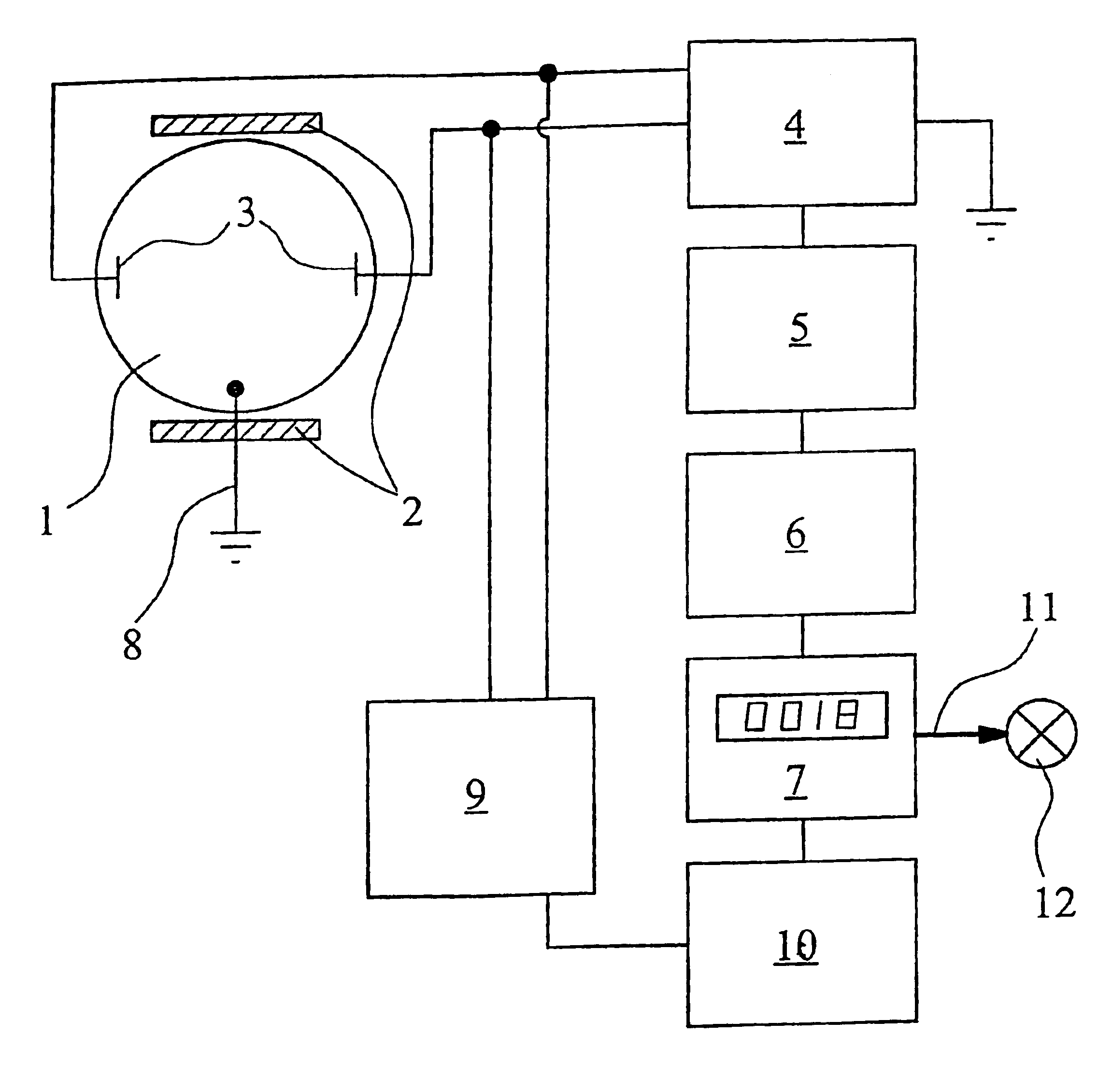
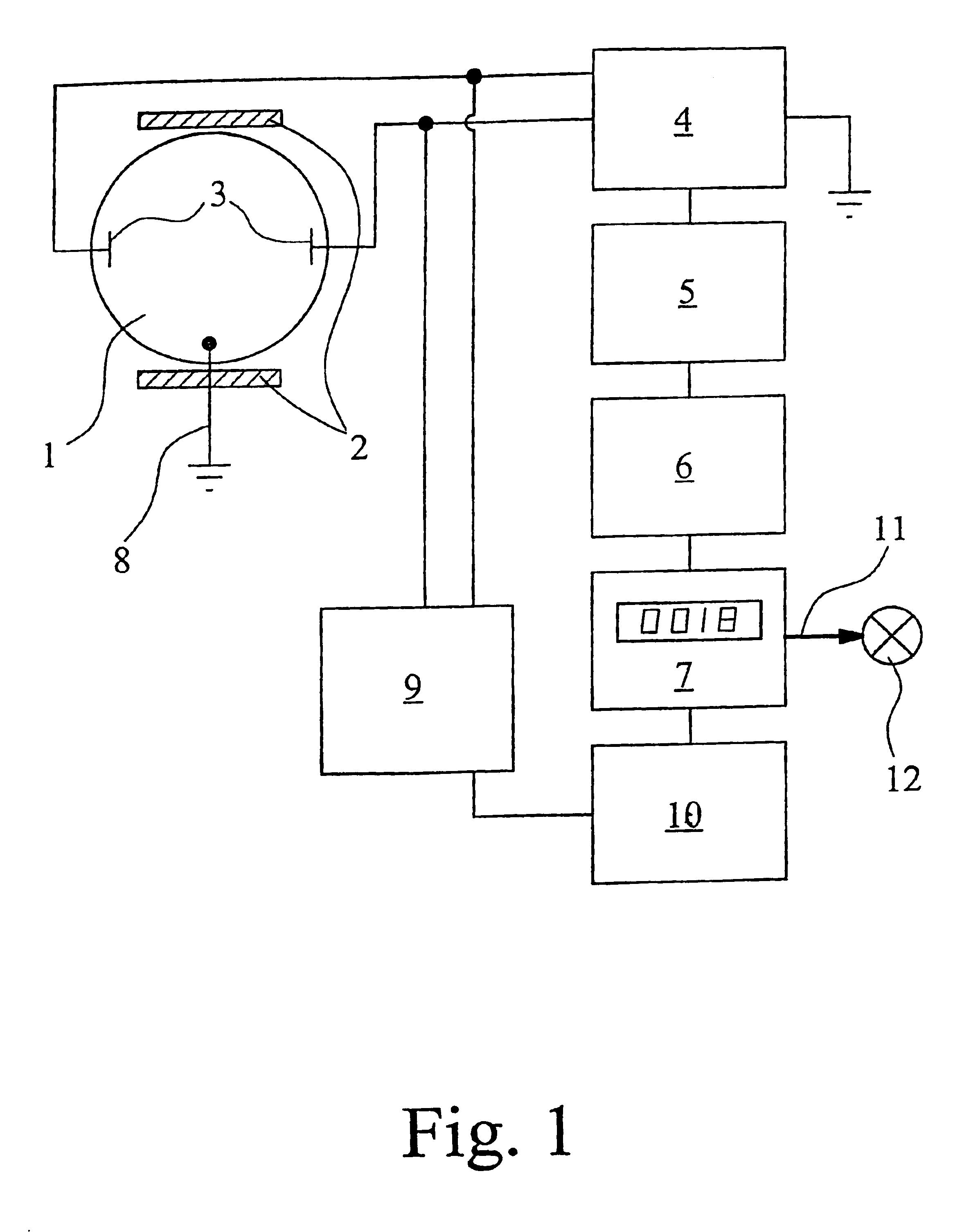
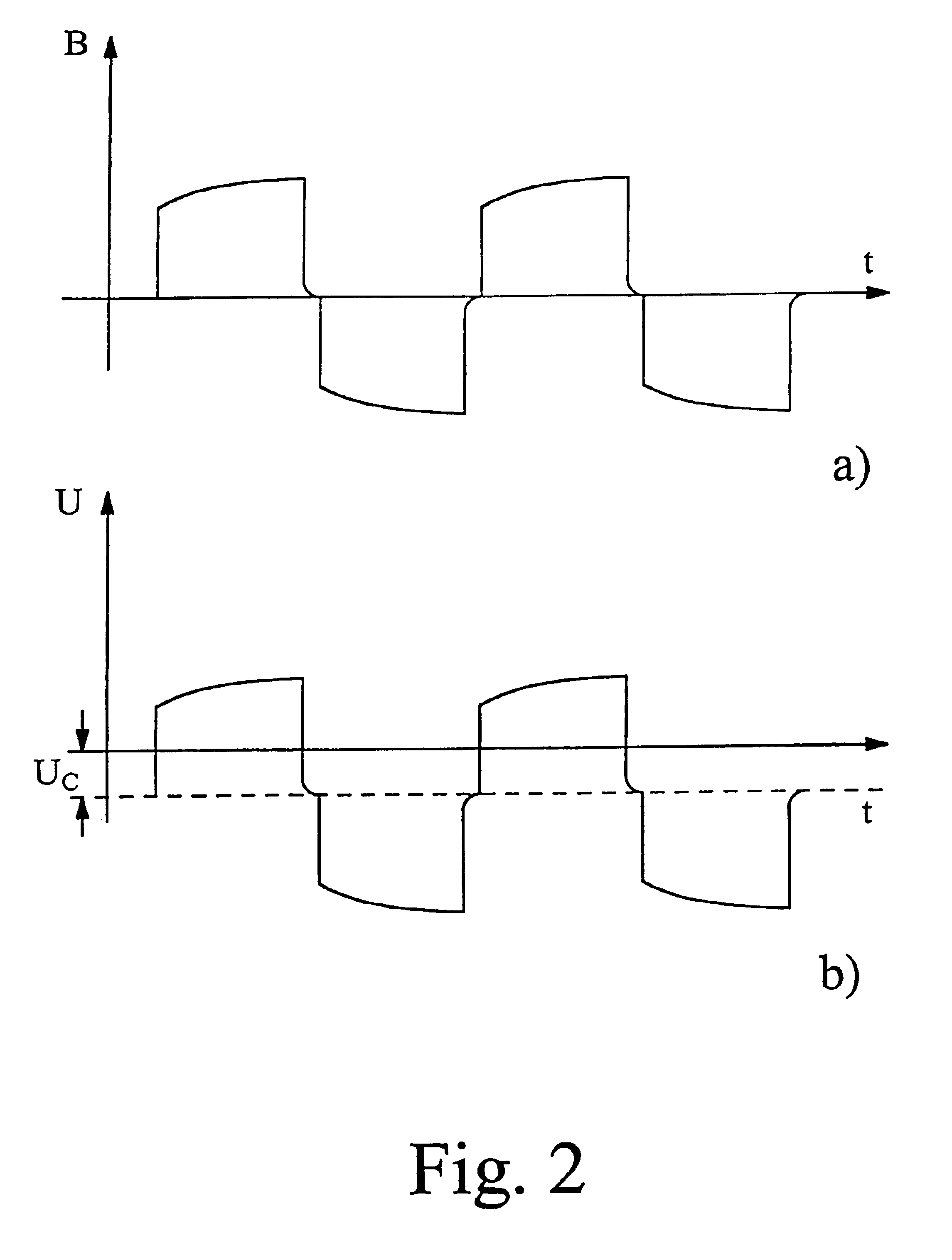
. 1 is a schematic representation of the structure of a magnetoinductive flowmeter according to a preferred embodiment of the invention. The magnetoinductive flowmeter incorporates a measuring tube 1, a magnet with two field coils 2, and two measuring electrodes 3. The measuring electrodes 3 are conductively connected to the fluid flowing through the measuring tube 1. The field coils 2 generate a periodically alternating magnetic field which extends in a direction essentially perpendicular to the axis of the measuring tube. The preferred embodiment of this invention here illustrated and described employs a magnetic field which in time-controlled fashion follows an essentially rectangular or square-wave pattern and is periodically polarity-reversed as shown in FIG. 2a. The measuring electrodes are so positioned that the imaginary line between them extends in a direction perpendicular to the axis of the measuring tube and in a direction perpendicular to the vector of the periodically ...


PUM


Abstract

A magnetoinductive flowmeter incorporates a measuring tube, a magnet serving to generate a periodically alternating magnetic field that extends in a direction at least essentially perpendicular to the axis of the measuring tube, and two measuring electrodes positioned along a connecting line that extends in a direction at least essentially perpendicular to the axis of the measuring tube and to the vector of the magnetic field. An output device is provided by means of which a value for the constant-voltage component of the voltage collected at one or both of the measuring electrodes and differentiated from a reference potential is displayed to the user and / or is made available to the user for further processing. An equivalent flow-measuring process is also described.

Description

1. Field of the InventionThis invention relates to a magnetoinductive flowmeter for moving fluids, incorporating a measuring tube, a magnet serving to generate a periodically alternating magnetic field that extends in a direction at least essentially perpendicular to the axis of the measuring tube, and two measuring electrodes positioned along a connecting line that extends in a direction at least essentially perpendicular to the axis of the measuring tube and to the vector of the magnetic field. The invention further relates to a magnetoinductive flow-measuring process for measuring the flow rate of a fluid moving through a measuring tube which is equipped with two measuring electrodes positioned along a connecting line that extends in an at least essentially perpendicular direction relative to the axis of the measuring tube, in which process a periodically alternating magnetic field is generated that extends in a direction at least essentially perpendicular to the axis of the meas...

Claims


Application Information

Patent Timeline
Patent Type & Authority Patents(United States)
IPC IPC(8): G01F1/56G01F1/60
CPCG01F1/60
Inventor BROCKHAUS, HELMUT
Owner KROHNE MESSTECHNICK GMBH & CO KG
Why Eureka
Try Eureka