Liquid photometer using surface tension to contain sample

a surface tension and liquid photometer technology, applied in the field of ultra-low volume instruments, can solve the problems of difficult and/or time-consuming cleaning of these cells or cuvettes for use with another sample, difficult to establish a collimated optical light path of known length through such confined liquids,

Inactive Publication Date: 2004-10-26
NANODROP TECH LLC
View PDF7 Cites 127 Cited by
  • Summary
  • Abstract
  • Description
  • Claims
  • Application Information

AI Technical Summary

Benefits of technology

The invention is an optical instrument for photometric, spectrophotometric, fluorometric or spectrofluorometric analysis of liquids contained between two substantially parallel surfaces on anvils spaced apart a known distance, wherein the sample liquid is confined by the surfaces and the surface tension of the liquid. At least two optical fibers penetrate these surfaces. One fiber is the source and the other the receiver. Ordinarily each of the surfaces contains an optical fiber. These fibers are mounted coaxially with and perpendicular to the parallel confining surfaces. The shape and nature of the surfaces serve to confine the liquid so as to center the confined droplet in the optical path of the optical fibers imbedded in the surfaces. An apparatus supporting the surfaces permits the surfaces to be controllably separated tho allow loading of the sample and cleaning of the surfaces after sample analysis as well as to pull a column of controlled length in the sample to set the optical path length during measurement. The surfaces can be separated enough that both surfaces can have a nanodrop applied so that mixing or reacting can be carried out and observed. The surfaces can be moved into a close position for sample compression as a wetting aid or, in some instances, as an alternate loading position.

Problems solved by technology

When dealing with very small sample volumes of say from 1 to 2 microliters, it is difficult to create cells or cuvettes small enough to to be filled and permit the industry standard 1 cm optical path to be used.
It is also difficult and / or time consuming to clean these cells or cuvettes for use with another sample.
Although liquids confined by surface tension and an optical surface are well known, e.g. raindrops on the window, establishing a collimated optical light path of known length through such confined liquids has been perceived as difficult.

Method used


Image

  • Liquid photometer using surface tension to contain sample
  • Liquid photometer using surface tension to contain sample
  • Liquid photometer using surface tension to contain sample

Examples


Embodiment Construction

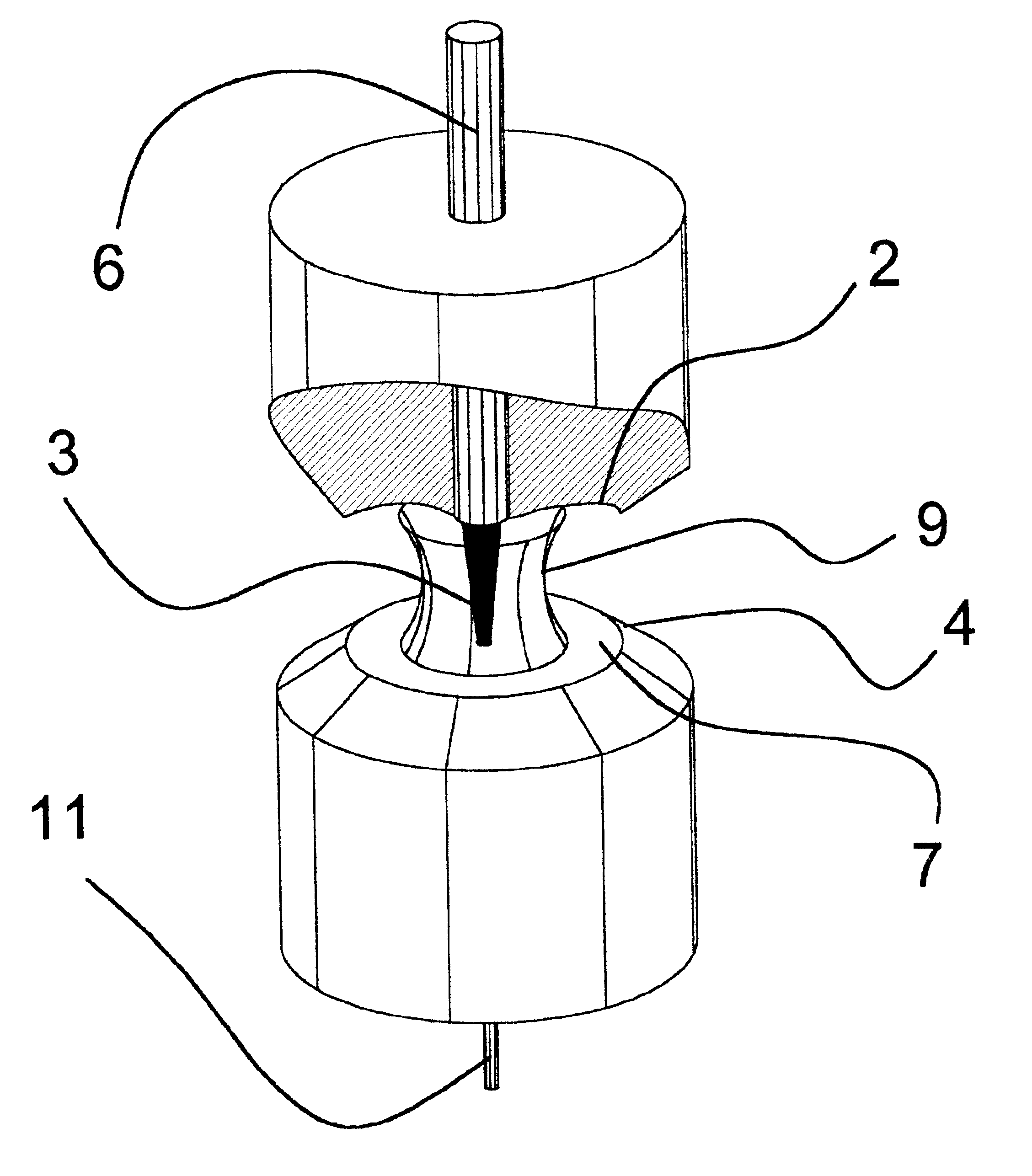
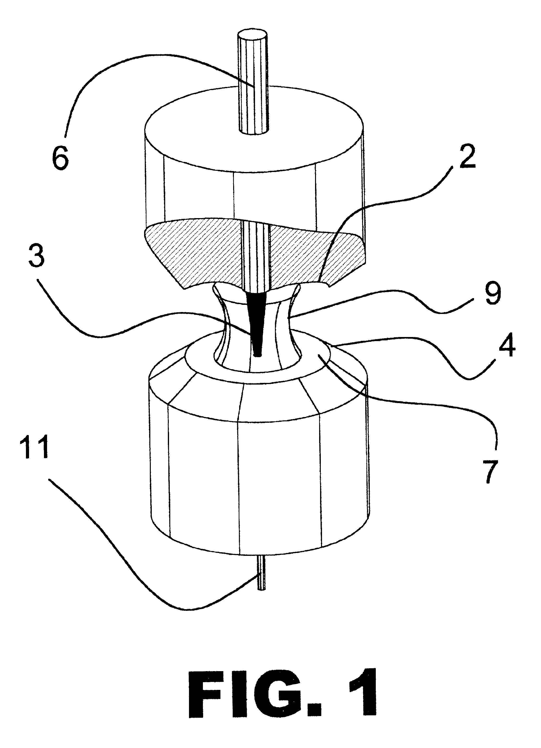
The liquid sample shown in FIG. 1 is contained by its surface tension between surfaces 2 and 7 also shown in FIG. 1. Light 3 from the system source (such as 74 in FIG. 4a) coming through the fiber 11 contained in surface 7 radiates upward 3 through the liquid sample 9 and is collected by the larger fiber or light pipe 6 in the upper surface 2 and sent on to the analysis photometer or spectrometer (such as 70 in FIG. 4a) for absorbance measurements.

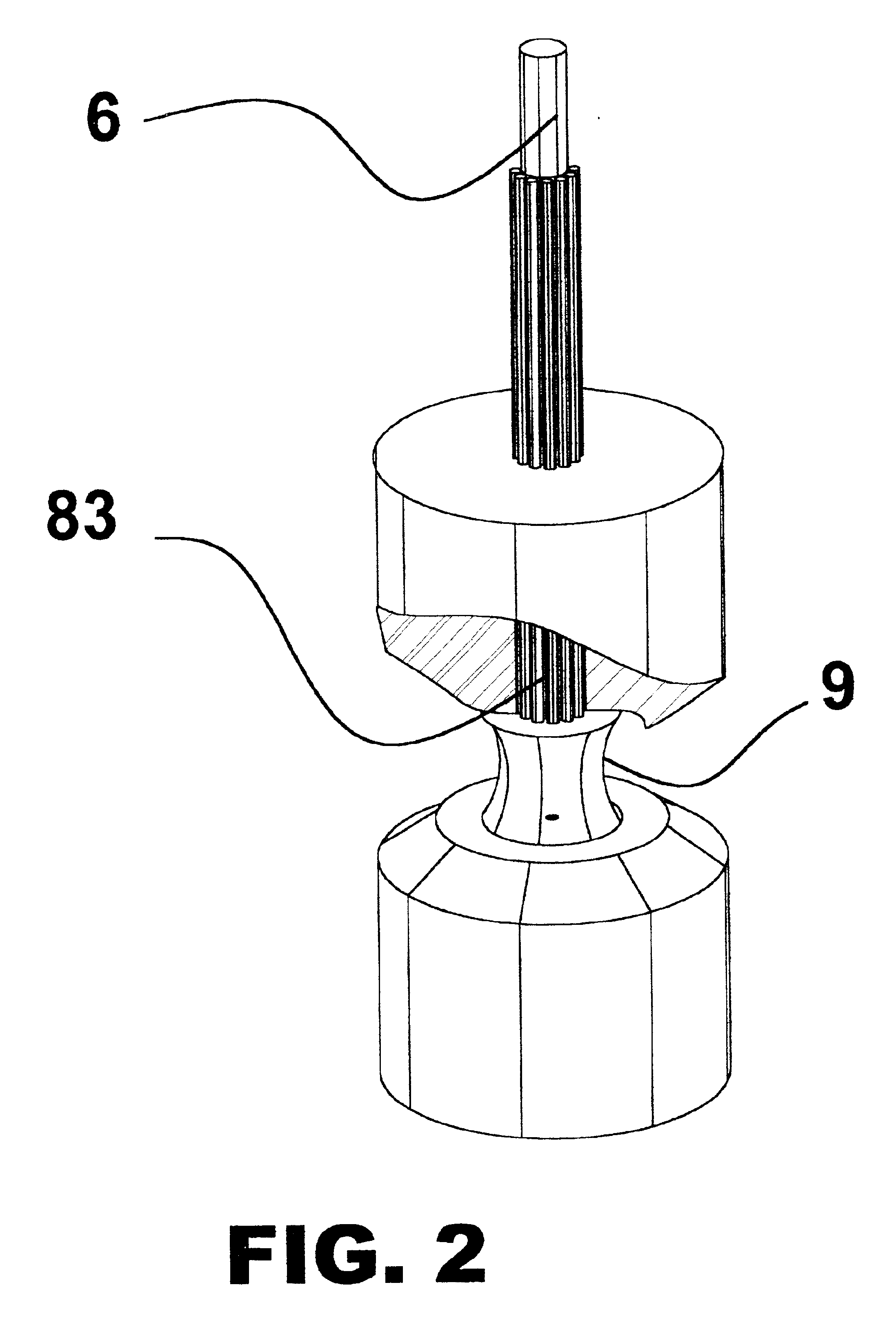
Measurements of the level of fluorescence of samples can be made by adding an excitation filter to the light source (not shown) and an emission filter to the detector (also not shown) to specifically reject all light from the excitation source at the detector. The level of fluorescence will, thus, be directly dependent on the length of the optical path between the anvils. The excitation can also be brought to the sample 9 through fibers 83 surrounding the collection fiber 6 as is shown in FIG. 2. This reduces the need for a high level of e...


PUM

PropertyMeasurementUnit
volumeaaaaaaaaaa
diameteraaaaaaaaaa
volumesaaaaaaaaaa

Abstract

Method and apparatus of spectroscopy or the like on extremely small samples in which a drop is held between two opposing surfaces by surface tension and one surface is controllably toward and away from the other. To provide and transmit exciting energy through the drop for measurement, optical fibers go through a surface and finish flush with the surface. One of the surfaces can be swung clear of the other for easy cleaning between tests. Means for determining wetted surface are provided.

Description

The invention relates to the fields of photometry, spectrophotometry, fluorometry, spectrofluorometry and the like and their use in optically quantitating and or characterizing liquids and solutions.BACKGROUND OF INVENTIONThis invention relates to the field of spectrophotometers and related instruments. More particularly the invention relates to ultra low volume instruments working in the volume range of 2 microliters or less. Such devices are particularly useful in quantitation of biotechnology samples including nucleic acids or proteins where it is desirable to keep sample loss and / or cross-contamination to a minimum.Robertson, in International Publication Number WO 01 / 14855, discloses method and apparatus for liquid photometry on extremely small samples. Robertson is the inventor of the instant invention which is an improvement thereon The disclosure, of the publication is incorporated herein by reference. A U.S. nation stage application was entered into for that reference and ha...

Claims


Application Information

Patent Timeline
Patent Type & Authority Patents(United States)
IPC IPC(8): G01N21/01
CPCB82Y15/00G01N21/01G01N2021/035
Inventor ROBERTSON, CHARLES WILLIAM
Owner NANODROP TECH LLC
Why Eureka
Try Eureka