Method and apparatus for preparation of molded glass

a technology of molded glass and molded glass, which is applied in the field of forming molds, can solve the problems of frame aberration, inability to manufacture with high production efficiency molded glass products having high surface precision, and tendency to shrinkag

Inactive Publication Date: 2004-11-09
HOYA CORP
View PDF4 Cites 45 Cited by
  • Summary
  • Abstract
  • Description
  • Claims
  • Application Information

AI Technical Summary

Problems solved by technology

Additionally, shrinkage tends to occur when the mold is released at a temperature exceeding the glass transition point.
However, it has become clear that the following problems tend to occur due to the mold structure in the molding method employing this fo

Method used


Image

  • Method and apparatus for preparation of molded glass
  • Method and apparatus for preparation of molded glass
  • Method and apparatus for preparation of molded glass

Examples


embodiment 1

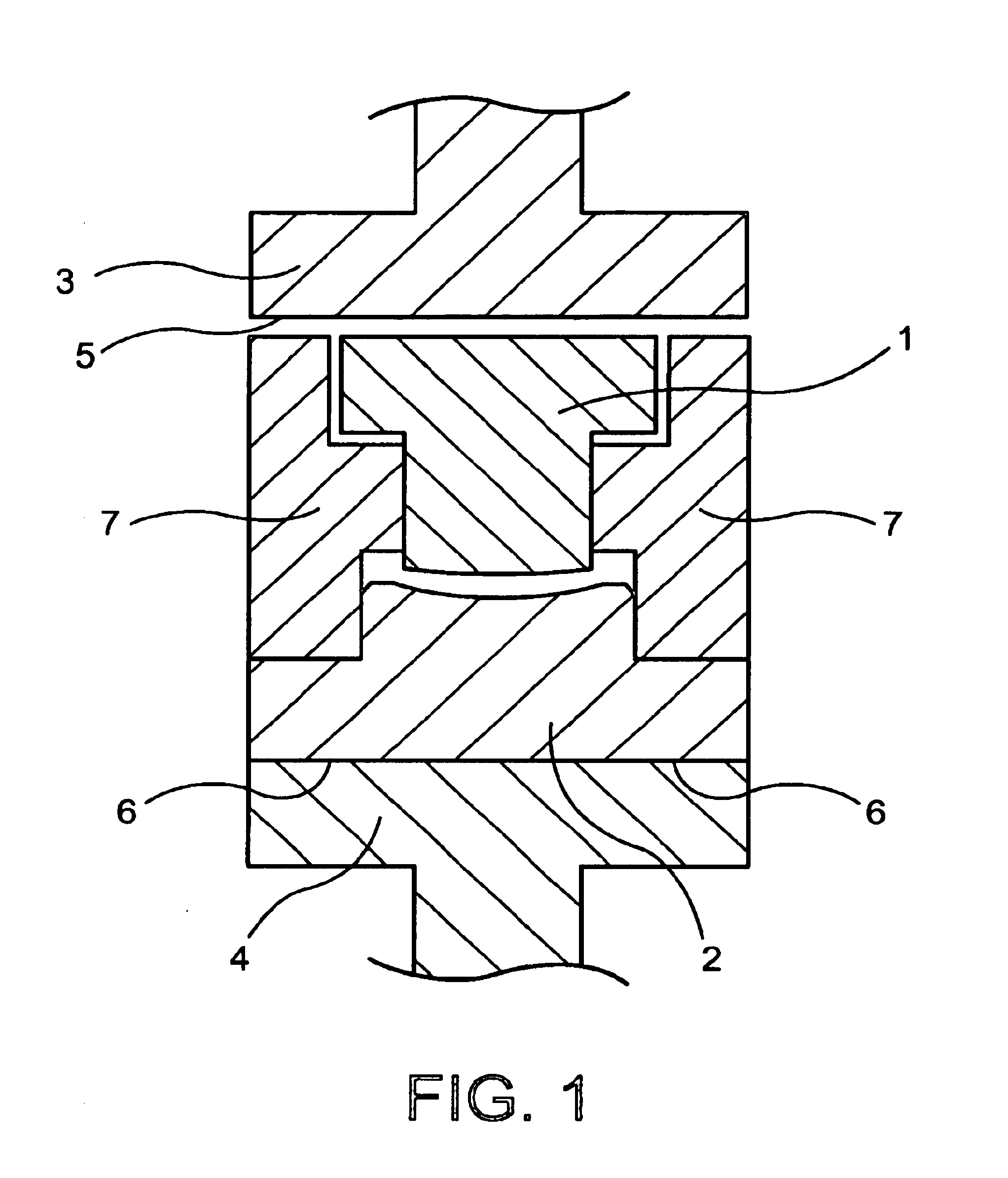
FIG. 1 shows the method of assembling the molded glass article manufacturing device of the present invention. FIG. 1(a) [sic] shows the forming mold set on the pressing shaft (not shown). Upper mold 1 and lower mold 2 are comprised of a binderless ultrahard alloy and the forming surfaces thereof are coated with a protective film in the form of a thin film of Pt--Rh--Au--Ir alloy.

Upper main shaft 3 and lower main shaft 4 are precisely aligned. Upper main shaft 3 and lower main shaft 4 can be mold support members connecting the forming molds (upper mold 1 and lower mold 2) to the main shafts. That is, in FIG. 1, upper mold 1 is directly secured to upper main shaft 3 and lower mold 2 is directly secured to lower main shaft 4. However, mold support members can be present between upper mold 1 and main upper shaft 3, and lower mold 2 and main lower mold 4, and the forming molds and main shafts indirectly secured.

The lower surface 5 of main upper shaft 3 and the upper surface 6 of main low...

embodiment 2

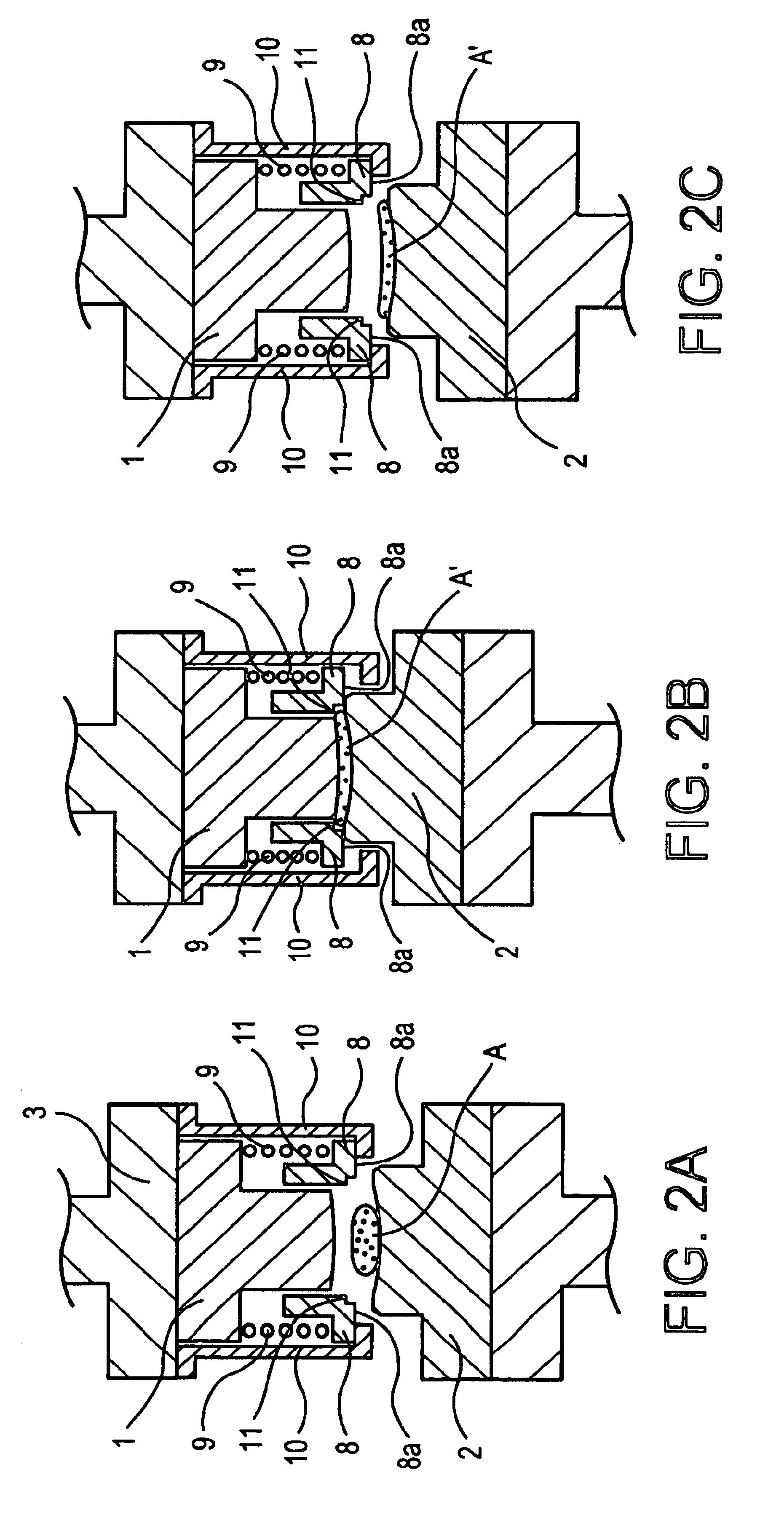
FIG. 3 shows the molding device employed in Embodiment 2. The difference between the molding device employed in Embodiment 1 and the molding device shown in FIG. 3 is the position of spring 9. In the molding device shown in FIG. 2, spring 9 is positioned between mold separating ring 8 and upper mold 1, while in the device shown in FIG. 3, spring 9 is positioned between mold separating ring 8 and main upper shaft 3. In the present embodiment, as in Embodiment 1, the device shown in FIG. 3 was employed to mold a 20 mm press diameter convex meniscus lens. The molded glass article obtained was extremely good from the viewpoints of thickness, surface precision, axial shift, and tilt. The outer diameter [portion] was removed in a subsequent step, yielding the final product.

embodiment 3

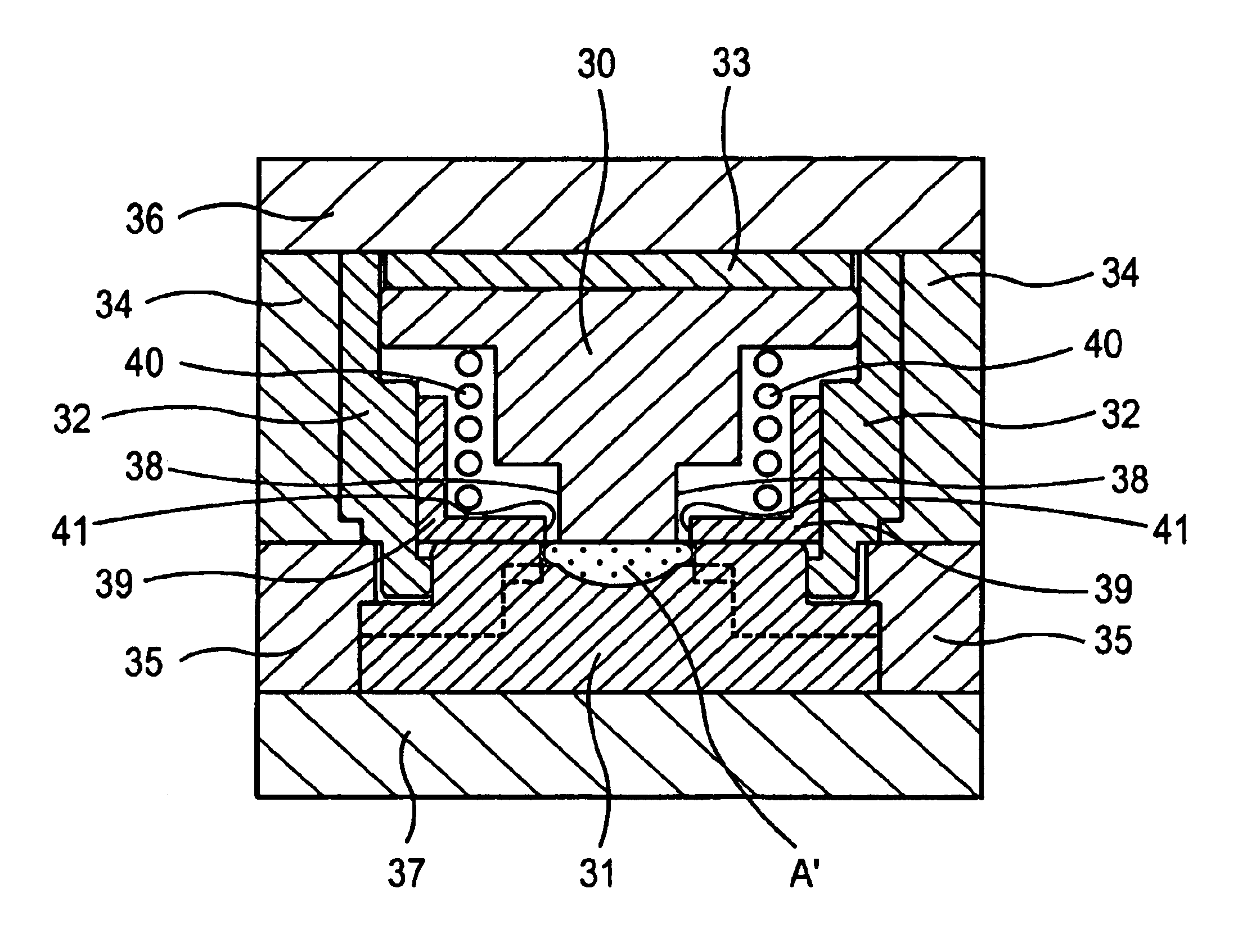
A laser optical system microlens (object lens) was molded in the present embodiment using the molding device shown in FIG. 4. The outer diameter of the lens was determined by press molding.

The molding device shown in FIG. 4 comprises an upper mold forming unit that is approximately cylindrical and chiefly comprises an upper mold 12, an upper sleeve 14, and an upper plate 16, and a lower mold forming unit consisting of a lower mold 13, a lower sleeve 15, and a lower plate 17. Lower mold 13 and lower sleeve 15 can also be an integrated structure. Further, upper sleeve 14 is equivalent to a drum. Specifically, the upper mold forming unit comprises a disk-shaped upper plate 16; a hollow cylindrical upper sleeve 14 positioned beneath upper plate 16 and secured to upper plate 16; an upper mold 12 inserted into upper sleeve 14, positioned concentrically with upper sleeve 14, and having a forming surface on its lower end that presses down upon and forms a glass material; a mold separating r...


PUM

PropertyMeasurementUnit
Temperatureaaaaaaaaaa
Shrinkageaaaaaaaaaa
Diameteraaaaaaaaaa

Abstract

A molded glass article manufacturing device, having a means of forcefully separating a molded glass article attached to the forming surface of an upper mold or a lower mold, and readily and reliably aligning the axes of the upper mold and lower mold, a molded glass article manufacturing method, and a method of assembling a molded glass article manufacturing device are provided. A molded glass article manufacturing device comprising a drum capable of regulating an upper mold and a lower mold having opposing forming surfaces so that the displacement axes thereof align; a forced mold separating means separating a molded glass article adhered to a forming surface from the mold by contact with at least the rim portion of the molded glass object; and a displacement means for displacing said forced mold separating means relative to said upper mold or said lower mold so that, in the course of separation of said upper mold and said lower mold, said forced mold separating means contacts at least the rim portion of said molded glass article and separates said molded glass article from the forming surface. Further, a manufacturing method for molded glass articles employing this device and a method of assembling molded glass article manufacturing devices are disclosed.

Description

This application claims priority under 35 U.S.C. .sctn..sctn. 119 and / or 365 to 311458 / 1999 filed in Japan on Nov. 1, 1999; the entire content of which is hereby incorporated by reference.1. Technical FieldThe present invention relates to forming molds that are suited to the manufacture of molded glass articles such as high-precision lenses and do not require cutting or polishing following press molding. The present invention also relates to methods of molding glass articles employing these forming molds. The present invention further relates to methods of assembling formed glass article manufacturing devices suited to the manufacture of formed glass articles such as high-precision lenses.2. Background ArtA great number of techniques for producing molded glass articles such as high-precision lenses by forming in mold presses have been developed in recent years. These molding techniques can be divided into roughly two categories. In the first method, the glass material to be molded i...

Claims


Application Information

Patent Timeline
IPC IPC(8): C03B11/06C03B11/12C03B11/08
CPCC03B11/08C03B11/122C03B2215/73C03B2215/60C03B2215/68C03B2215/48Y02P40/57
Inventor HIROTA, SHINICHIROSUGAWARA, KISHIO
Owner HOYA CORP
Why Eureka
Try Eureka