Stator with one-way clutch

a one-way clutch and stator technology, applied in the field of stator, can solve the problems of difficult machined resilient pieces and relatively expensive bushes

Inactive Publication Date: 2004-11-09
NSK WARNER
View PDF9 Cites 19 Cited by
  • Summary
  • Abstract
  • Description
  • Claims
  • Application Information

AI Technical Summary

Benefits of technology

As the stator according to the present invention is constructed as described above, the provision of the plain bearing and the side plate as discrete members and the arrangement of the plain bearing in engagement with its corresponding side plate have made it possible to provide the stator with a reduced dimension in the axial direction. Further, the plain bearing and side plate can be formed at low cost by subjecting plate-shaped blanks to pressing which is an easy machining method. When these plain bearing and side plate are arranged in a form engaged with each other via the engageable portions, they can show performance at least comparable with conventional bearings although the stator is available at low cost.

Problems solved by technology

As a corollary to this, such bushes are relatively expensive.
This example, however, involves a problem in that any attempt to shorten the axial length of the one-way clutch makes it difficult to machine resilient pieces, which are required to produce an outer cage drag, into cages.

Method used


Image

  • Stator with one-way clutch
  • Stator with one-way clutch
  • Stator with one-way clutch

Examples


Embodiment Construction

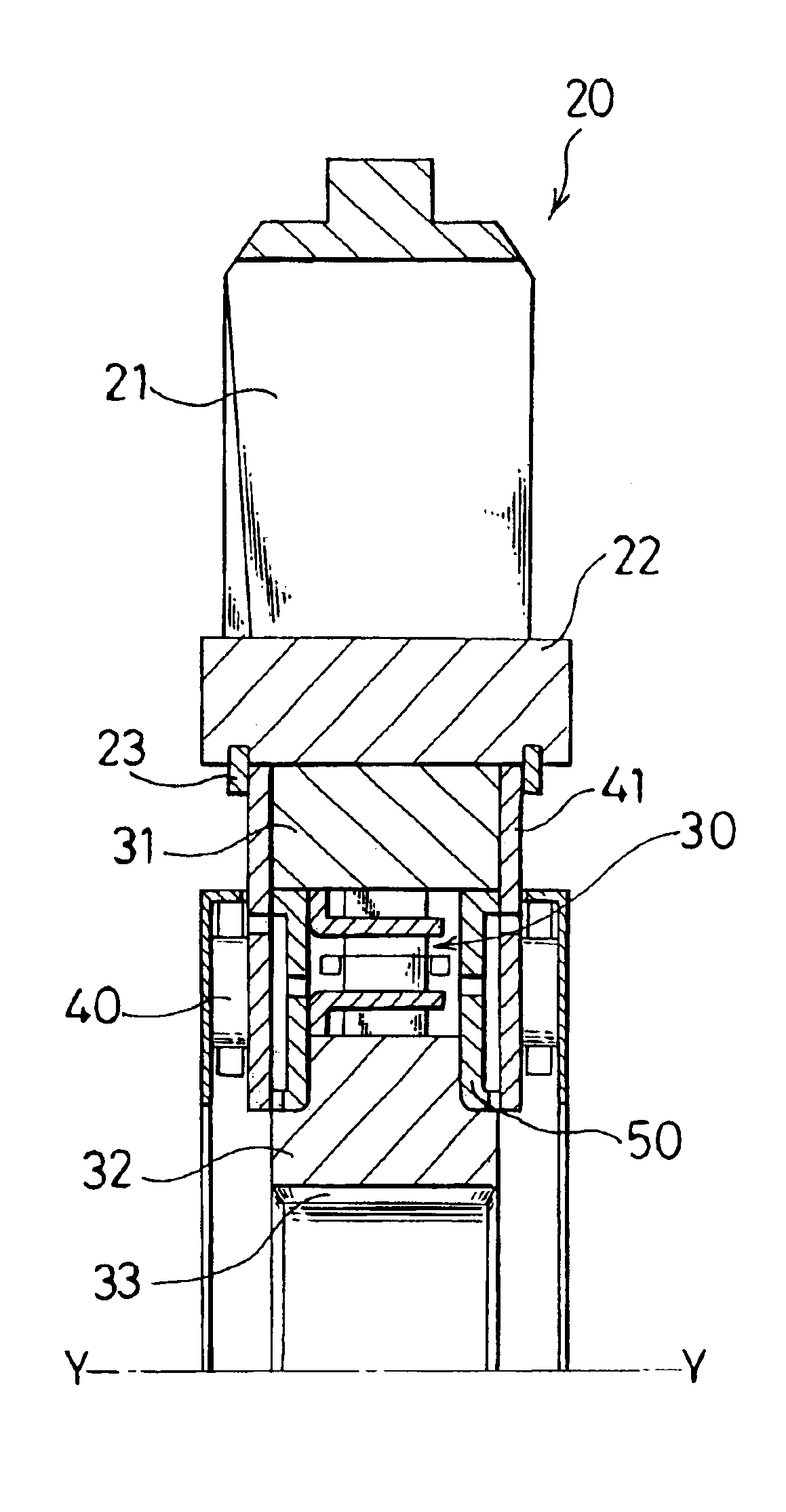
With reference to FIG. 1 to FIG. 3, the stator according to the one embodiment of the present invention will hereinafter be described. The stator, which is designated generally by numeral 20 and is useful in a torque converter, has an impeller 21 secured on a radially inner, cylindrical part 22. Arranged between the radially inner, cylindrical part 22 and a central fixing part (not shown) is the one-way clutch which is designated at numeral 30. There are also illustrated an outer ring 31 and an inner ring 32 of the one-way clutch 30, splines 33 on the inner ring 32, and a central axis Y--Y. The splines 33 are in engagement with the central fixing part.

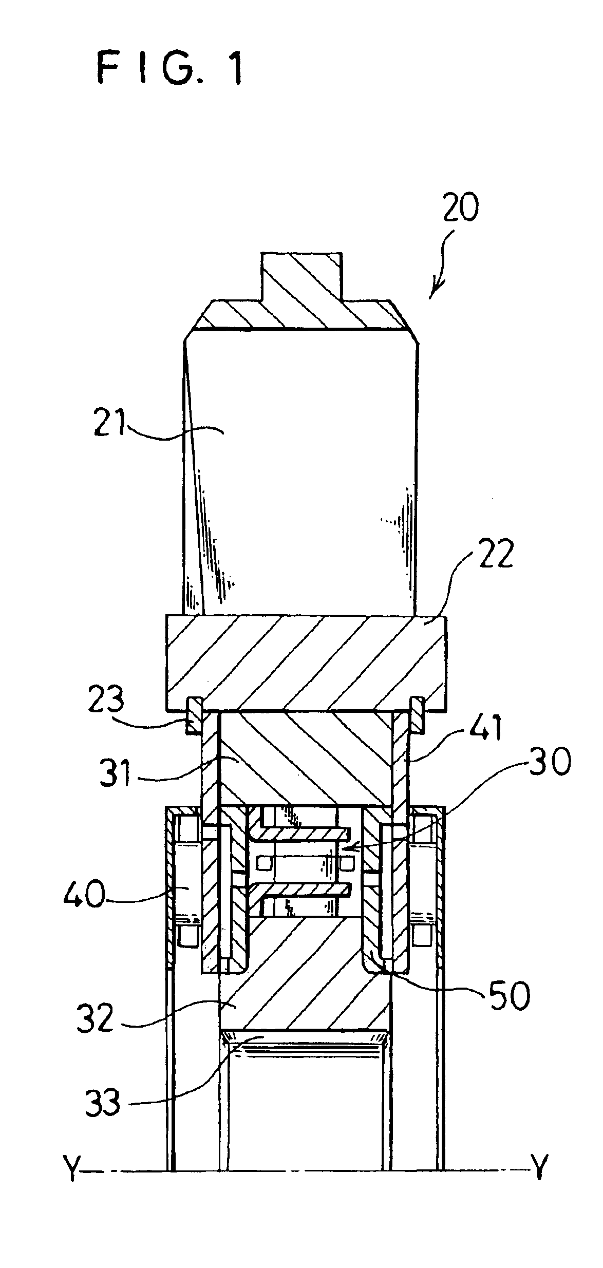
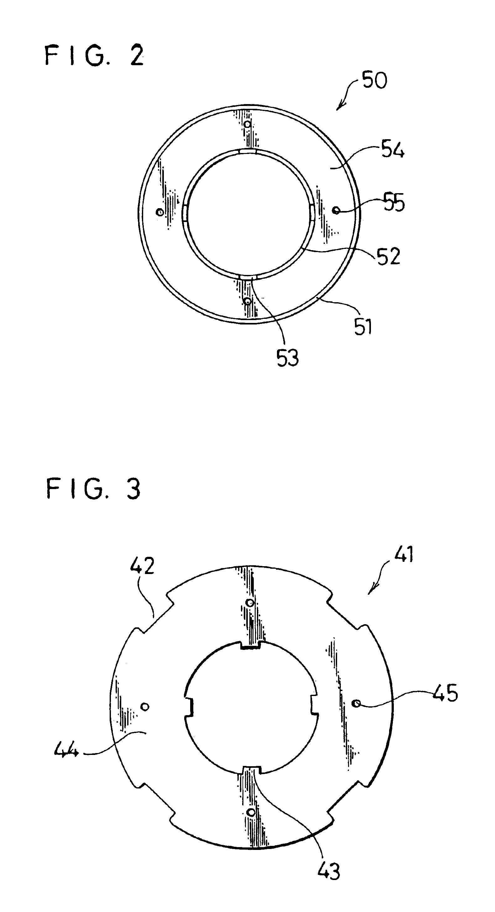
The outer ring 31 and the inner ring 32 are supported by plain bearings 50. In the present invention, the plain bearings 50 and the side plates 41 are arranged as discrete members in place of bushes, and the plain bearings 50 are arranged in engagement with their corresponding side plates 41. As illustrated in FIG. 1 and FIG. 2, each p...


PUM


Abstract

A stator is provided with an impeller and a one-way clutch. The stator includes at least one plain bearing and at least one side plate. The plain bearing is arranged adjacent to and on an axially outer side of a side portion of the one-way clutch and between an inner ring and an outer ring of the one-way clutch, and on its inner and outer peripheries, has flanges with bearing tracks formed thereon. The side plate is arranged on an axially outer side of the plain bearing and at a position adjacent to the plain bearing such that the side plate serves not only as a stopper for the plain bearing but also as a bearing track for a needle bearing. The plain bearing and side plate are provided with engageable portions, respectively, and are maintained in engagement with each other via the engageable portions.

Description

a) Field of the InventionThis invention relates to a stator, which is provided with a one-way clutch and is useful in a torque converter.b) Description of the Related ArtIn FIG. 4, a conventional stator 10 provided with a one-way clutch is shown. In the drawing, numeral 21 indicates an impeller of the stator 10, while numeral 22 designates a radially-inner, cylindrical part of the impeller. On an inner periphery of the radially-inner, cylindrical part 22, a one-way clutch 30 is arranged. Designated at numerals 31,32 are an outer ring and an inner ring of the one-way clutch 30, respectively. The outer and inner rings 31,32 are both rotatably supported on bushes 35. Aluminum alloys have been used primarily as materials of such bushes in order to allow the bushes to exhibit a bearing function. The bushes 35 also serve as bearing tracks for needle bearings 40 disposed on axially-outer sides of the one-way clutch 30, respectively. These bushes 35 are provided with lubrication holes to su...

Claims


Application Information

Patent Timeline
Patent Type & Authority Patents(United States)
IPC IPC(8): F16D41/00F16D41/07F16C33/06F16H41/24
CPCF16D41/07F16H2041/246F16H41/24F16D2041/0601
Inventor KAMIYA, TAIJISHIRATAKI, HIROBUMI
Owner NSK WARNER
Why Eureka
Try Eureka