Serrated cable core

a cable core and cable technology, applied in the field of cable cores, can solve the problems of insufficient damage to the cable portion, unable to connect to the extreme end of the cylinder, and rendering the cable non-functional,

Inactive Publication Date: 2004-11-09
BELDEN TECHNOLOGY INC
View PDF27 Cites 84 Cited by
  • Summary
  • Abstract
  • Description
  • Claims
  • Application Information

AI Technical Summary

Problems solved by technology

Connecting to the extreme ends of the cylinder can be difficult, so generally a portion of the outermost tubes of the cables are stripped off the ends of the cable for a predetermined longitudinal distance from the end of the cable.
This requires the stripping machine to be able to exert a particular force which is great enough to fully separate and strip off the undesired portions of the cable, but is not sufficient to damage the portions of the cable which are not to be removed.
With the advent of these machines, it was discovered that for the machine to be able to effectively remove the inner layer(s) (particularly the innermost insulator, often called the insulation, from the innermost conductor), such force was required on the pull step that the inner conductor(s) and inner insulator(s) (the cable core) would be pulled from within the cable, rendering the cable non-functional.
The problem with these methods is that they often do not solve the underlying issue of the stripping machine damaging the cable while attempting to strip it, and may add unnecessary cost.
Tighter jackets or heat generated bonds often result in too much resistance between the components causing the stripping machine to fail to strip the cable and instead only partially separating the layers creating an unusable portion.

Method used


Image

  • Serrated cable core
  • Serrated cable core
  • Serrated cable core

Examples


Embodiment Construction

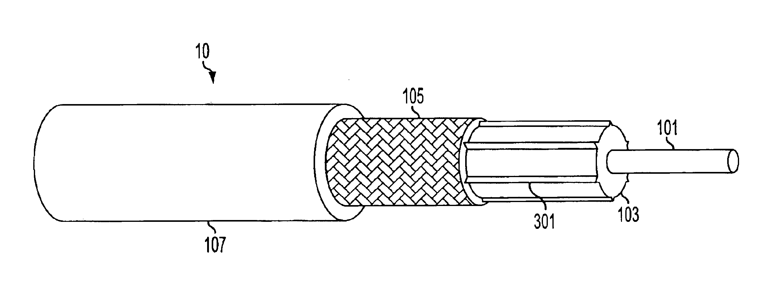
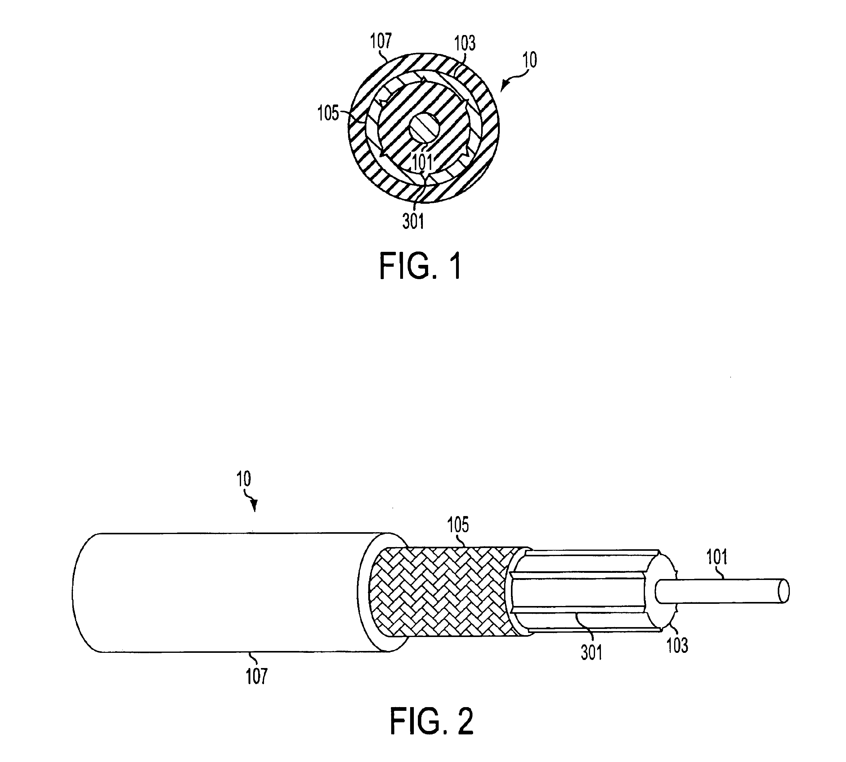
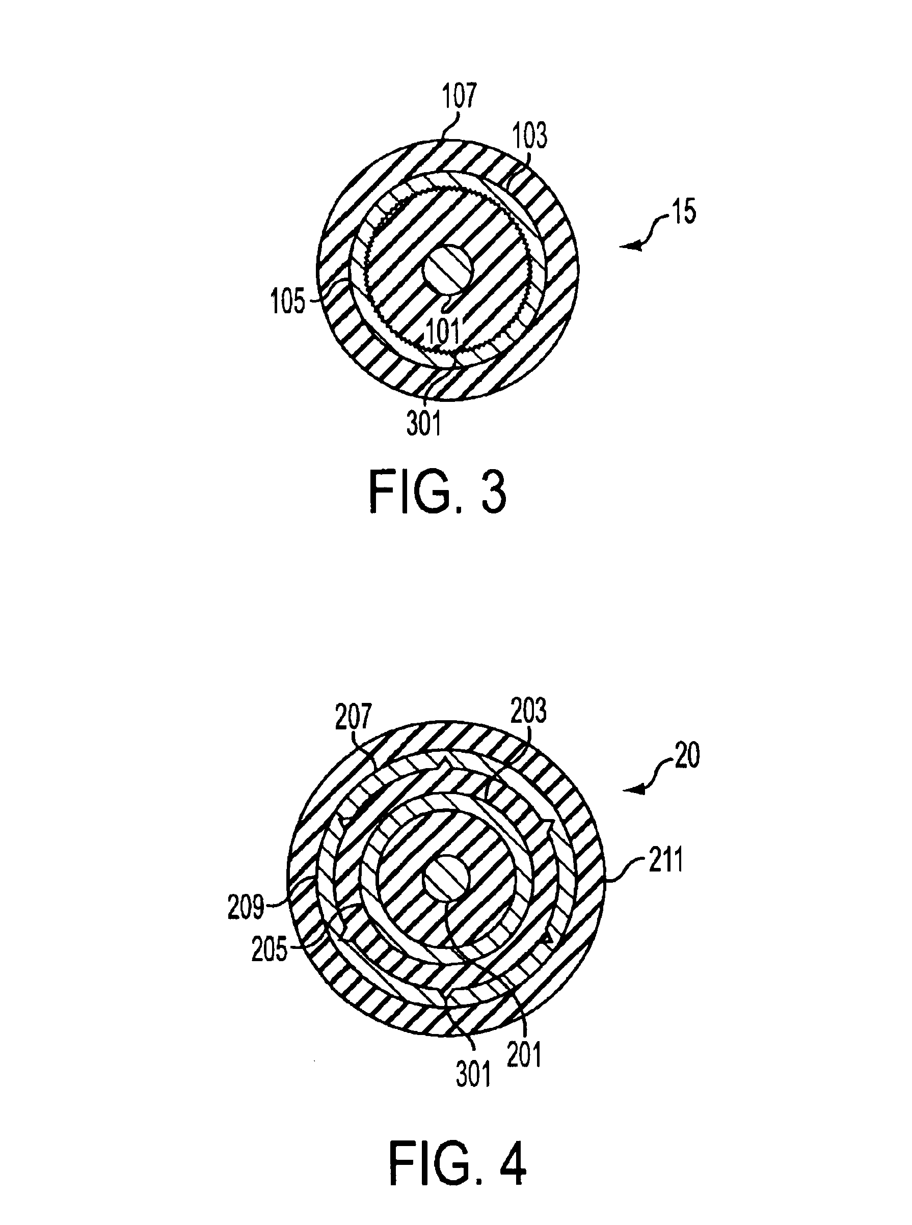
Although the cables and methods described below are discussed primarily in terms of their application to axially arranged cables such as, but not limited to, coaxial, triaxial, twinaxial, and armored cables for use with automatic stripping equipment, it would be understood by one of ordinary skill in the art that the principles, methods, and devices disclosed herein could also be used on other types of axially arranged cable, for other types of cables, and / or for cables either not designed to be stripped, or stripped by hand. Further, cables incorporating the principles, methods, or devices described herein can be used to carry any type of signal and can be attached to any type of connector or terminator for use in any environment.

The use of the term "serrated" or "serrations" in this disclosure will generally be used to refer to an object having teeth, ridges, peaks, points, projections and / or protrusions extending from the surface thereof. These serrations can be of any shape and ...


PUM

PropertyMeasurementUnit
diameteraaaaaaaaaa
metallicaaaaaaaaaa
shapeaaaaaaaaaa

Abstract

An axially arranged cable, such as a coaxial, triaxial, twinaxial, or armored cable which includes at least one serration on an insulative or conductive layer internal thereto and methods of manufacturing the same. These serrations may appear on insulators or inner jackets and are in physical contact with conductive layers such as shields which axially surround the insulative layers. The serrations generally increase the contact force between the insulative layers and the conductiver layers to help prevent separation of the cable core during stripping of the axial cable.

Description

1. Field of the InventionThis disclosure relates to the field of cables. In particular to coaxial and triaxial cables for use with automatic stripping equipment.2. Description of the Related ArtIn the modern world, cables are everywhere. They are used to transmit numerous signals between individual electronic components which can range from the very basic building blocks of electrical systems to the most cutting-edge consumer and commercial devices. One of the most common of these is the coaxial cable which can be used for everything from connecting a DVD player to a TV, to connecting sophisticated medical apparatus to processing computers, to hooking up components of computer or telecommunications networks.As the coaxial cable (and the related triaxial cable) have come into increased use in both consumer and commercial contexts, the need for more and more finished cable assemblies to be produced has become greater. While cable can be manufactured on large rolls using modern assembl...

Claims


Application Information

Patent Timeline
Patent Type & Authority Patents(United States)
IPC IPC(8): H01B11/18
CPCH01B11/1834
Inventor GEBS, BERNHART ALLENCLEMENTE, BENJAMIN PERALEJO
Owner BELDEN TECHNOLOGY INC
Why Eureka
Try Eureka