
Prismatic wood compression molding method and compression molding device therefor

a molding method and wood technology, applied in the field of wood compression molding method, can solve the problems of large volume of wood in a large container, large size of die set for compressing long wood, and low manufacturing efficiency

Inactive Publication Date: 2004-11-16
SHINSHU UNIVERSITY +1
View PDF13 Cites 2 Cited by
  • Summary
  • Abstract
  • Description
  • Claims
  • Application Information

AI Technical Summary

Benefits of technology

This method allows for the efficient and cost-effective manufacturing of long, prismatic wood with a polygonal cross-section, enabling the use of damaged wood and reducing production costs while maintaining the structural integrity of the compressed shape.

Problems solved by technology

To heat-treat the wood in the container by steam, the container must be a pressure container, it is difficult to simultaneously treat a large amount of wood in a large container, and manufacturing efficiency must be lower.
If the wood to be compressed is longer than the compressing die set, it is difficult to compress the wood throughout length thereof, therefore size of the die set for compressing long wood must be large.
In the case of heating the raw wood whose water content is about 20%, vapor is emitted while heating; the compressing die set must be made of stainless steel, so that the compressing die set must be expensive and manufacturing cost of the compressed lumber must high.
Generally, length of prismatic pillars for wooden building are several meters, so it is very difficult to compress long wood by the method disclosed in the Japanese patent gazette due to size of the compressing die set and the manufacturing cost.

Method used


Image

  • Prismatic wood compression molding method and compression molding device therefor
  • Prismatic wood compression molding method and compression molding device therefor
  • Prismatic wood compression molding method and compression molding device therefor

Examples


Embodiment Construction

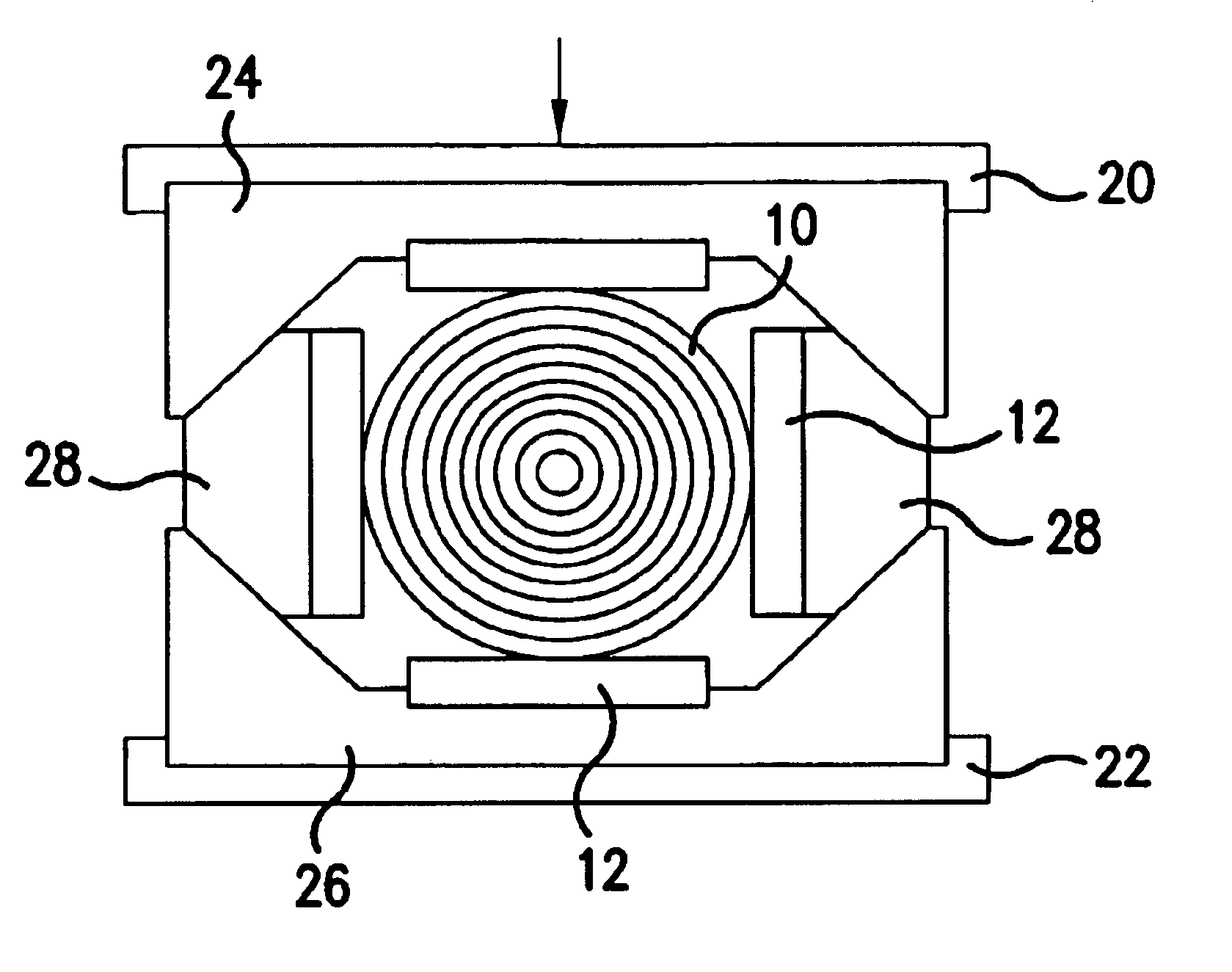
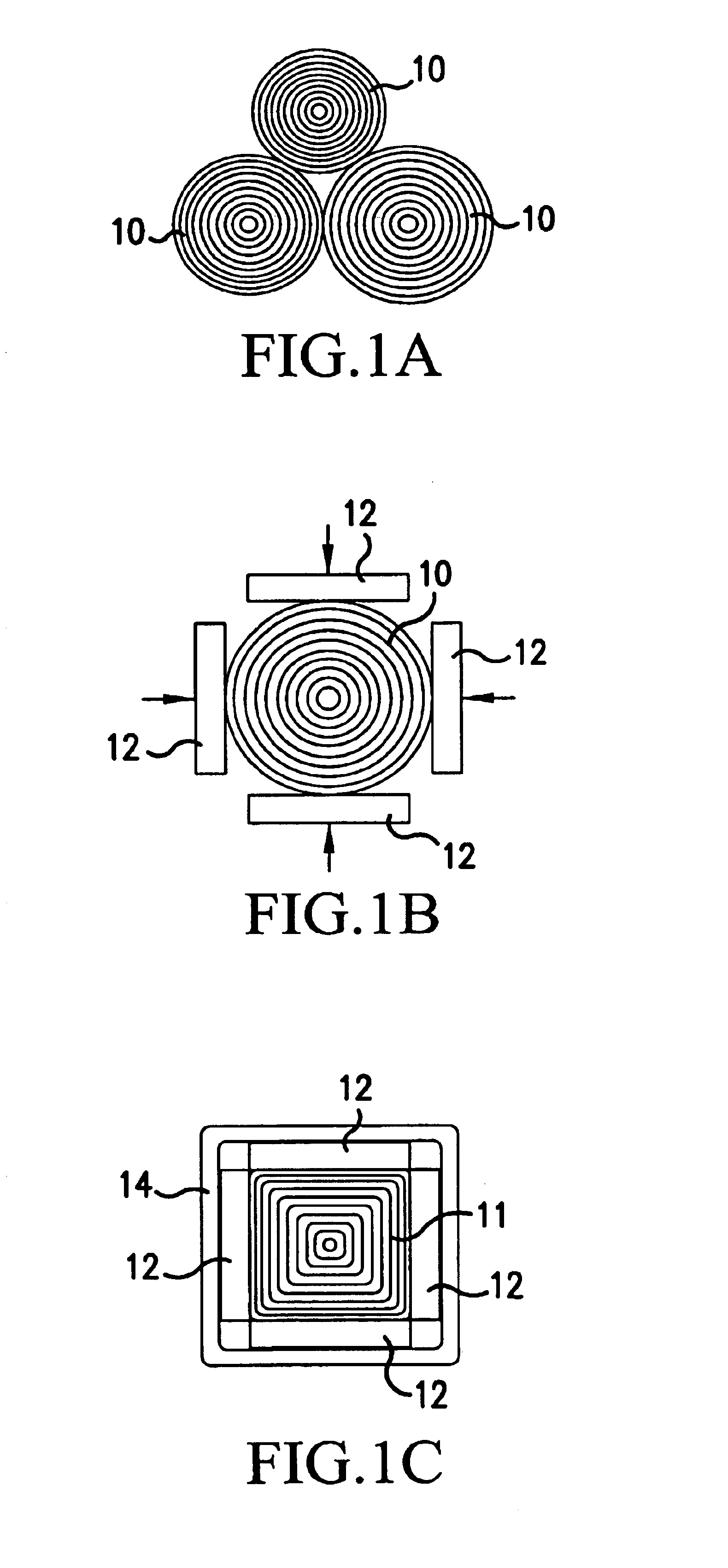
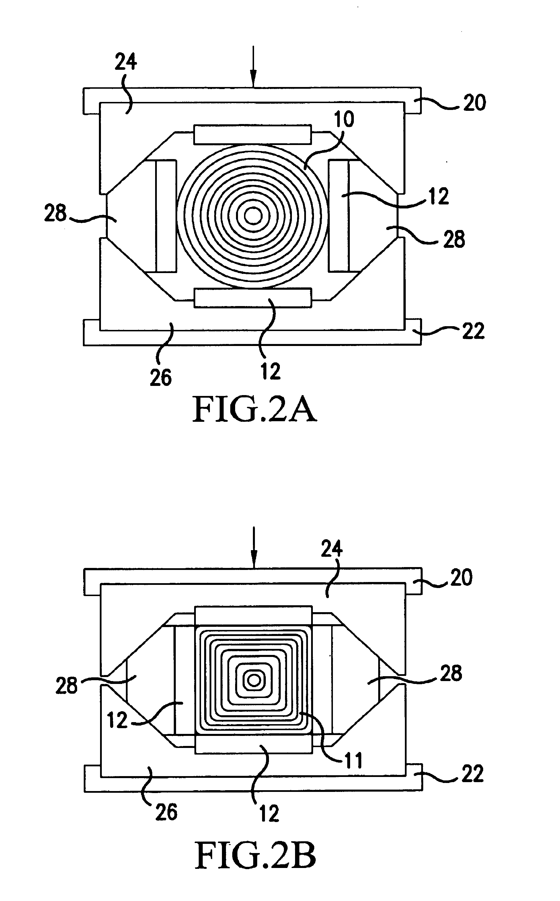
An example of the prismatic wood compression molding method of the present invention will be explained with reference to FIGS. 1A-1C and 2. In the method shown in FIGS. 1A-1C, 2A and 2B, a log 10 shown in FIG. 1A is compressed as wood to be compressed. The log 10 may have bark. As shown in FIG. 1B, metal plates 12 are arranged to enclose and contact the log 10, and the length of the metal plates are equal to that of the log. The metal plates 12 are respectively pressed by external force shown by arrows (directions perpendicular to the metal plates 12) shown in FIG. 1B, so that the outer circumferential face of the log 10 is compressed and formed into a prismatic shape.

The metal plates 12 are rigid plates, so the metal plates 12 are not deformed by the external force.

As shown in FIG. 1B, a two-axis compressing die set shown in FIG. 2 may be used so as to press the metal plates 12, 12 . . . and form the log 10 into the prismatic shape. The two-axis compressing die set comprises: an up...


PUM


Abstract

A prismatic wood compression molding method capable of easily producing long-sized lumber usable as pillars or like by compression molding. The method is characterized by comparing the steps of: using a plurality of rigid plate-like bodies such as metal plates to compress an outer face of wood throughout length thereof to compression-mold it into prismatic wood which is polygonal, such as rectangular or hexagonal, in cross section; restraining the plate-like bodies by a restraining jig so as to hold flat surfaces of the prismatic wood in a state in which they are compressed by the plate-like bodies; and applying a heat treatment to the prismatic wood held in the compressed state by the plate-like bodies and the jig so as to permanently fix the shape of the prismatic wood.

Description

FIELD OF TECHNOLOGYThe present invention relates to a prismatic wood compression molding method, more precisely relates to a prismatic wood compression molding method, in which prismatic wood having a polygonal sectional shape, e.g., rectangular, hexagonal, is formed by compressing wood, the compressed state of the wood is maintained and the compressed wood is heat-treated so as to permanently fix the prismatic shape of the compressed wood.BACKGROUND TECHNOLOGYConventionally, compressed lumber is manufactured by the steps of: compressing wood, e.g., needle-leaf wood; accommodating the compressed wood in a container; and heating the compressed wood by introducing steam into the container so as to permanently fix the shape of the compressed wood whose hardness is almost equal to that of broadleaf wood.To heat-treat the wood in the container by steam, the container must be a pressure container, it is difficult to simultaneously treat a large amount of wood in a large container, and man...

Claims


Application Information

Patent Timeline
Patent Type & Authority Patents(United States)
IPC IPC(8): B27M1/00B27M1/02B27K5/00
CPCB27M1/02
Inventor KITAZAWA, KIMIYOSHISHIBUYA, YORIKUNI
Owner SHINSHU UNIVERSITY
Learn More