Integrated coal gasification combined cycle power generator

a combined cycle and power generator technology, applied in the direction of machines/engines, mechanical equipment, combustion gas production, etc., can solve the problems of environmental pollution discharge, danger of excessive dependence on petroleum as a source of energy, and the long-term stable price and supply of clean fuels such as these fuels, and achieve the effect of long-term stable price and supply of clean fuels

Inactive Publication Date: 2004-11-30
KK TOSHIBA
View PDF8 Cites 94 Cited by
  • Summary
  • Abstract
  • Description
  • Claims
  • Application Information

AI Technical Summary

Problems solved by technology

However, although long-term, stable supply is possible, coal burning results in the discharge of environmental pollutants, such as CO.sub.2 and SO.sub.x.
However, the danger of excessive dependence on petroleum as a source of energy was pointed out by the petroleum crisis of the 1970s.
Considering this fact, long-term stable price and supply of a clean fuel, such as these fuels, is becoming hard.
Although the conventional IGCC shown in FIG. 16 uses the coal gasification syngas fuel, a clean fuel, and produces an NO.sub.x concentration within regulatory limits, there are some problems.
One of the problems is related to the improvement in the system thermal efficiency.
However, cooling the high-temperature section of the gas-turbine system 2 by combining the above-mentioned methods is already coming to the limit of system thermal efficiency.
However, this increase of the high-pressure cooling air supplied to the high-temperature section of the gas-turbine is not contributed to the expansion work of the gas turbine 14.
Therefore, the system thermal efficiency drops (deteriorates).
Further, even if a suitable combination among the forced convection cooling method, the film cooling method and the impingement cooling method, was available, a cooling performance as predicted by calculations could not be obtained because the impurities adhere to the gas-turbine nozzle blade and the gas-turbine rotor blade.

Method used


Image

  • Integrated coal gasification combined cycle power generator
  • Integrated coal gasification combined cycle power generator
  • Integrated coal gasification combined cycle power generator

Examples


first embodiment

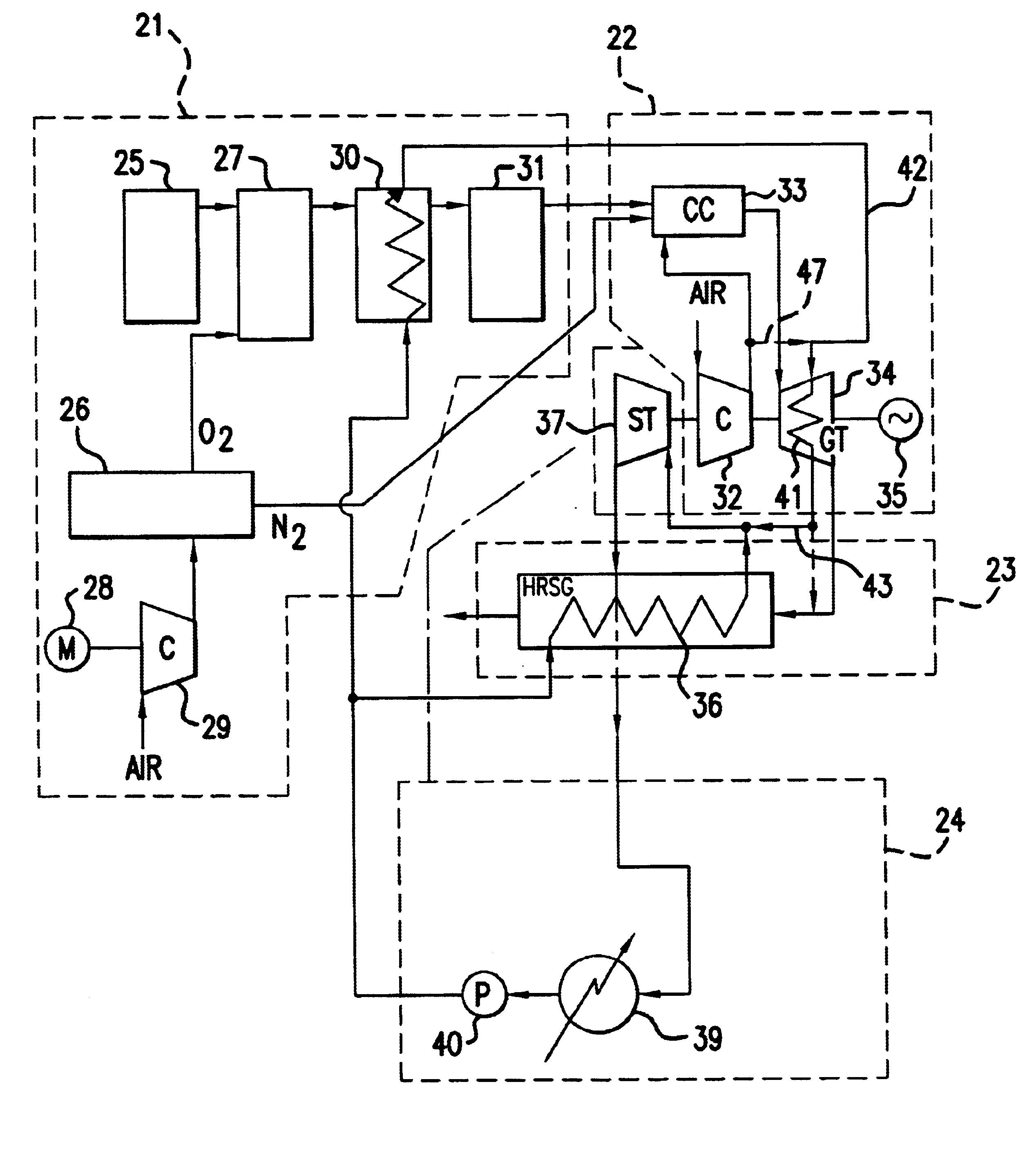
Referring now to the drawings, FIG. 1 provides a system diagram schematically showing an integrated coal gasification combined cycle power generator according to this invention.

The IGCC concerning this embodiment is constituted from a coal-gasification system 21, a gas-turbine system 22, an exhaust heat recovery boiler 23 and a steam turbine system 24.

In addition, although a heat recovery steam generator can be substituted for the exhaust heat recovery boiler 23, the following embodiments adopt the exhaust heat recovery boiler as heat recovery means.

The coal-gasification system 21 combines a coal supply portion 25, an oxygen system 26 and a coal gasifier 27. That is, in the coal-gasification system 21, a pulverized coal from the coal supply portion 25 and an oxygen gas from the oxygen system 26 are supplied to the coal gasifier 27.

A part of the pulverized coal is burned in the coal gasifier 27.

The remaining pulverized coal reacts according to the following formula, keeping the tempe...

second embodiment

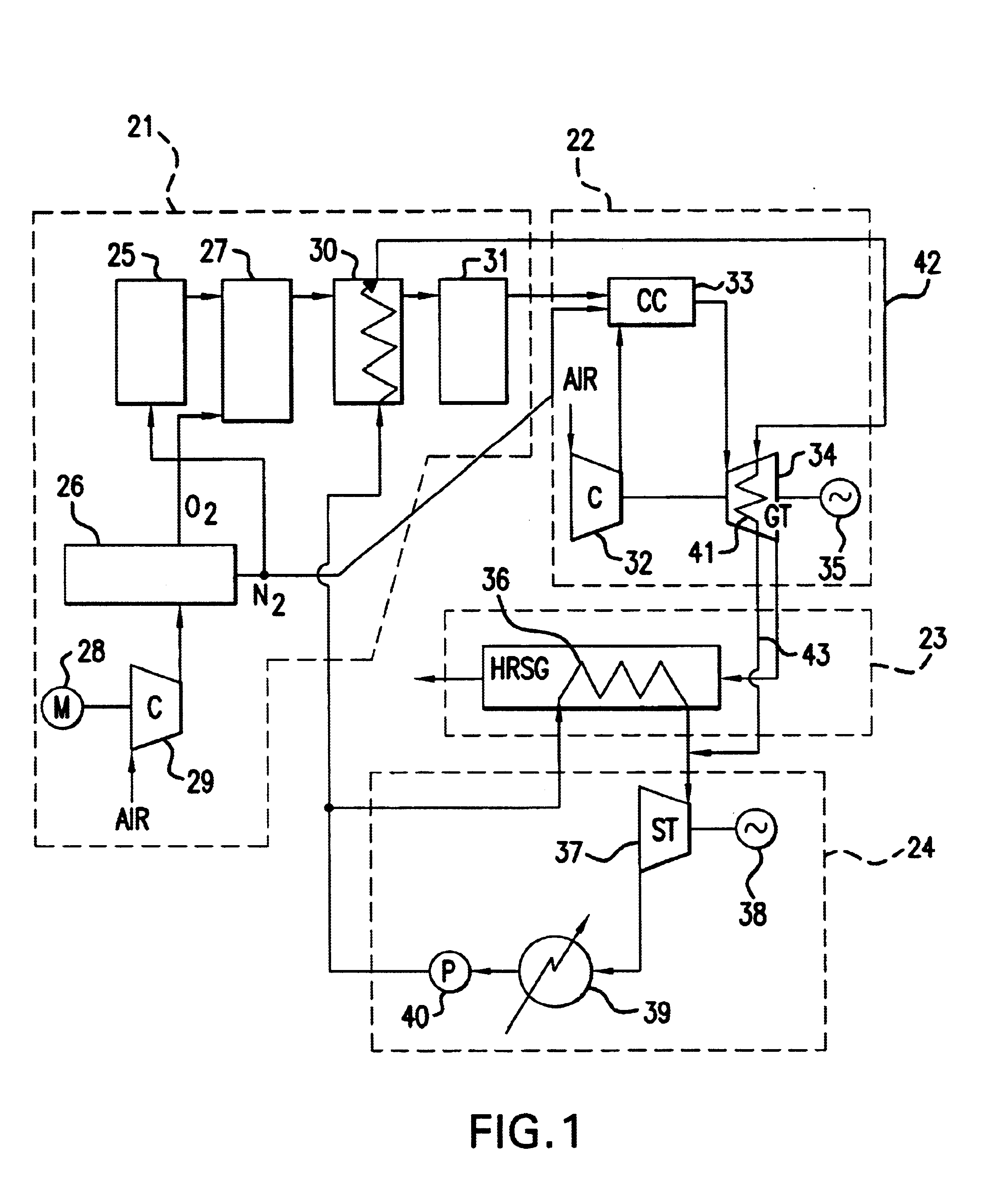
FIG. 2 is a system diagram schematically showing an integrated coal gasification combined cycle power generator according to this invention.

Those elements of FIG. 2 which are the same as in FIG. 1 have been given the same number as in FIG. 1. A discussion of those elements is not repeated. A similar protocol will be followed when discussing the other figures below.

The IGCC of the second embodiment, provides a cooling steam supply system 42 and a cooling steam recovery system 43. In this embodiment, the nitrogen gas is not supplied to the coal supplying equipment 25 because the coal supply portion 25 delivers a coal slury. Coal slury is conveyed to the coal gasifier 27 by a conveying equipment such as a pump (not shown).

The cooling steam supply system 42 is connected to the outlet side of a cooler 30 in a coal gasification system 20. It is also connected to the gas-turbine high-temperature section 41 in the gas turbine 34 through the combustor high-temperature section 44, such as a l...

third embodiment

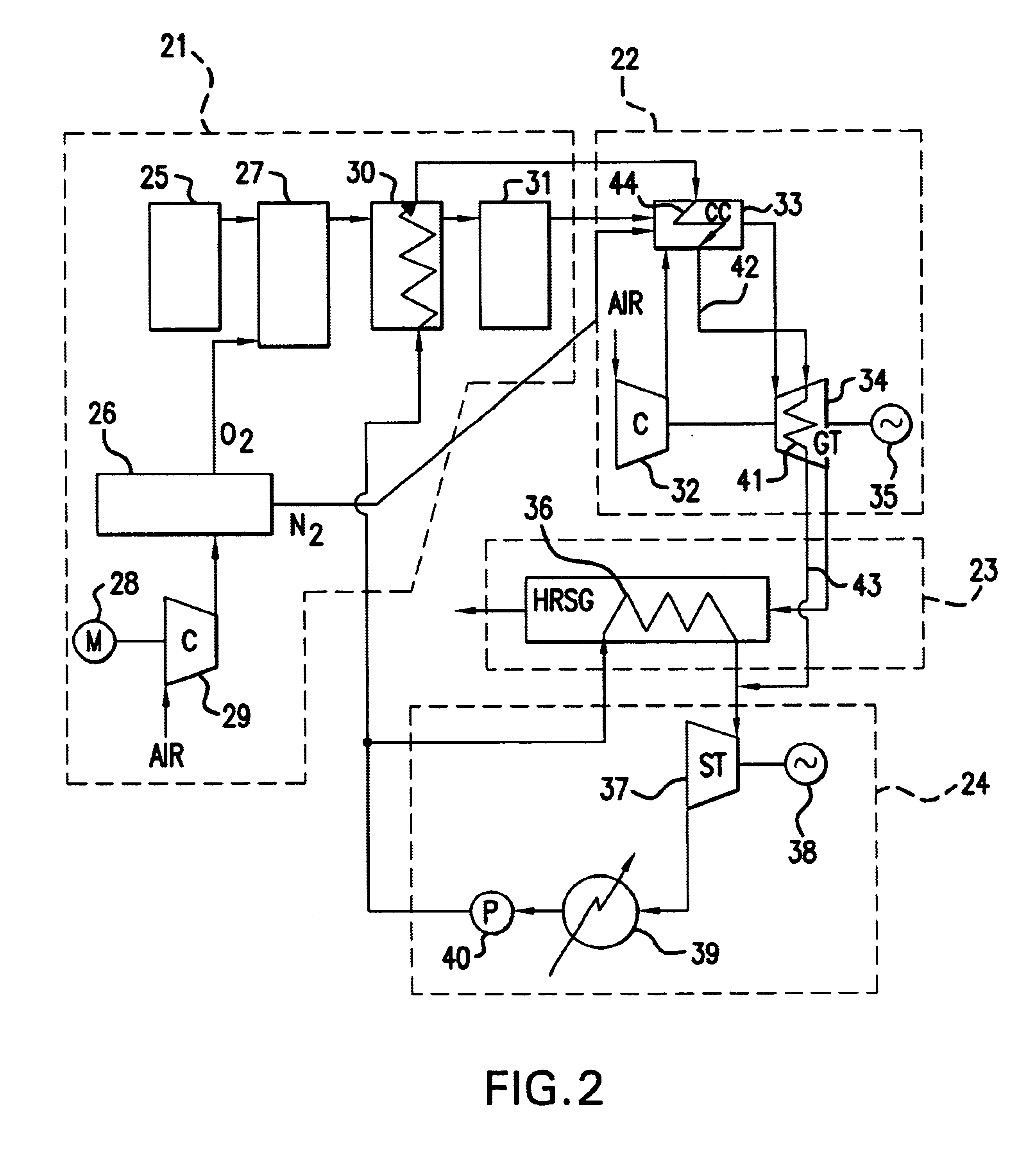
FIG. 3 is a system diagram schematically showing an integrated coal gasification combined cycle power generator according to this invention.

The embodiment depicted in FIG. 3 provides a cooling steam supply system 42 and a cooling steam recovery system 43. As this embodiment also utilizes a coal slury as fuel, the nitrogen gas is not supplied to the coal supply portion 25. That is, the coal slury is supplied by a conveying equipment such as a pump (not shown).

The steam supply system 42 connects to the outlet side of a cooler 30 in a coal-gasification system 21 and connects to a gas-turbine high-temperature section 41 of a gas turbine 34 through a combustor high-temperature section 44. The high-temperature section of the gas turbine combustor (33) may include the liner of a combustor the and transition piece.

The cooling steam recovery system 43 is connected to the outlet side of a gas-turbine high-temperature section 41 and is connected to a first heat exchanger 36, such as a medium-p...


PUM

PropertyMeasurementUnit
temperatureaaaaaaaaaa
pressureaaaaaaaaaa
heat efficiencyaaaaaaaaaa

Abstract

Embodiments of the invention provide an IGCC which achieves improved plant thermal efficiency by using a cooling steam supply system that cools the high-temperature sections of the gas turbine 34. Embodiments of the invention further provide and IGCC in which the cooling steam recovery system recovers steam after cooling the gas-turbine high-temperature section and makes practical re-use of the energy and substances within the system. Therefore, embodiments of the invention can reduce or eliminate the degradation of certain equipment by cooling the high-temperature sections. Methods are provided for increasing the thermal efficiency o an IGCC.

Description

The present invention relates to an Integrated Coal Gasification Combined Cycle Power Generator (hereinafter referred as IGCC.)DESCRIPTION OF THE RELATED ARTReducing the amount of the fossil fuel used and improving system heat efficiency is desired in the latest steam-generated power-generator systems.Coal, the fossil fuel used for steam-generated power-generator systems, is available in abundant amounts compared to petroleum or natural gas. Consequently, coal is cheaper than petroleum or natural gas. However, although long-term, stable supply is possible, coal burning results in the discharge of environmental pollutants, such as CO.sub.2 and SO.sub.x. For the above-mentioned reason, use of petroleum or the comparatively clean fuel from natural gas occupies the mainstream.However, the danger of excessive dependence on petroleum as a source of energy was pointed out by the petroleum crisis of the 1970s.Moreover, the estimated depletion years of a petroleum and a natural gas, quoting ...

Claims


Application Information

Patent Timeline
Patent Type & Authority Patents(United States)
IPC IPC(8): F01K23/06F02C3/26F02C3/28F01K23/10F02C7/18F01D5/08
CPCF01K23/068F02C3/28Y02E20/16Y02E20/18
Inventor OTOMO, FUMIOFUKUYAMA, YOSHITAKEUCHIDA, TATSUROUTSUNOMIYA, MASAHARUIIJIMA, HIROMITSUABURATANI, YOSHIHIRO
Owner KK TOSHIBA
Why Eureka
Try Eureka