
Real-time hardware memory scrubbing

a hardware memory and real-time technology, applied in the field of memory protection, can solve the problems of capacitors used to store charges, inherently susceptible to errors, and a greater potential for errors

Inactive Publication Date: 2004-12-14
SK HYNIX INC
View PDF15 Cites 82 Cited by
  • Summary
  • Abstract
  • Description
  • Claims
  • Application Information

AI Technical Summary

Benefits of technology

The present invention relates to a technique for detecting and correcting errors in a memory device. The invention addresses the problem of soft errors in semiconductor memory devices, which are caused by extraneous charged particles and can result in system failures or unnecessary system failures if not detected and corrected. The invention provides a method for identifying and correcting soft errors in a memory device, which can mitigate the risk of system failure and improve the reliability of the memory device. The invention also addresses the drawbacks of existing error detection and correction methods, such as the inability to detect and correct multi-bit errors and the slowing down of system processing due to the error detection process.

Problems solved by technology

These capacitors are inherently susceptible to errors.
As memory devices get smaller and smaller, the capacitors used to store the charges also become smaller thereby providing a greater potential for errors.
Hard errors are generally caused by poor solder joints, connector errors, and faulty capacitors in the memory device.
Hard errors are reoccurring errors which generally require some type of hardware correction such as replacement of a connector or memory device.
Soft errors, which cause the vast majority of errors in semiconductor memory, are transient events wherein extraneous charged particles cause a change in the charge stored in one or more of the capacitors in the memory device.
Because these soft errors are transient events, generally caused by alpha particles or cosmic rays for example, the errors are not generally repeatable and are generally related to erroneous charge storage rather than hardware errors.
Uncorrected soft errors will generally result in unnecessary system failures.
Further, soft errors may be mistaken for more serious system errors and may lead to the unnecessary replacement of a memory device.
However, in the case of multi-bit errors, (i.e., errors) which affect more than one bit, standard ECC methods may not be sufficient.
In some instances, ECC methods may be able to detect multi-bit errors, but not correct them.
In other instances, ECC methods may not even be sufficient to detect the error.
Thus, multi-bit errors must be detected and corrected by a more complex means since a system failure will typically result if the multi-bit errors are not detected and corrected.
Even in the case of single-bit errors which may be detectable and correctable by standard ECC methods, there are drawbacks to the present system of detecting and correcting errors.
One drawback of typical ECC methods is that multi-bit errors can only be detected but not corrected.
Further, typical ECC error detection may slow system processing since the error is logged and an interrupt routine is generated.
Also, harmless single-bit errors may align over time and result in an uncorrectable multi-bit error.
Because the error detection is generally implemented through software, the correction of single-bit errors may not occur immediately thereby increasing the risk and opportunity for single-bit errors to align, causing an uncorrectable error or system failure.

Method used


Image

  • Real-time hardware memory scrubbing
  • Real-time hardware memory scrubbing
  • Real-time hardware memory scrubbing

Examples


Embodiment Construction

One or more specific embodiments of the present invention will be described below. In an effort to provide a concise description of these embodiments, not all features of an actual implementation are described in the specification. It should be appreciated that in the development of any such actual implementation, as in any engineering or design project, numerous implementation-specific decisions must be made to achieve the developers' specific goals, such as compliance with system-related and business-related constraints, which may vary from one implementation to another. Moreover, it should be appreciated that such a development effort might be complex and time consuming, but would nevertheless be a routine undertaking of design, fabrication, and manufacture for those of ordinary skill having the benefit of this disclosure.

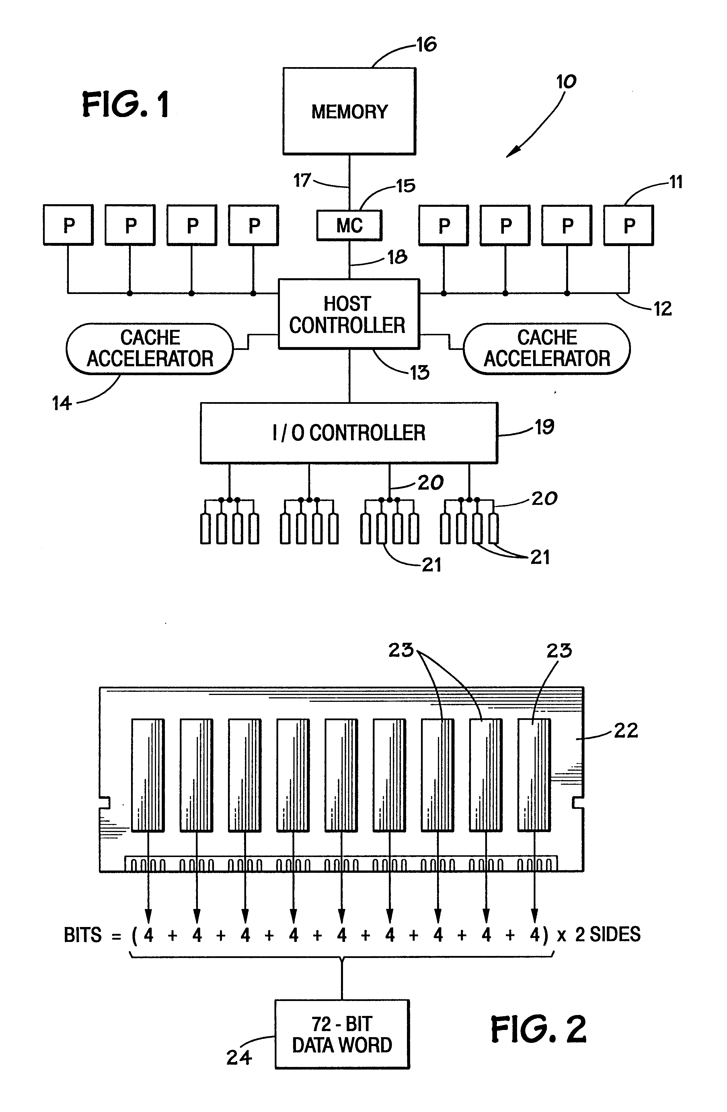
Turning now to the drawings, and referring initially to FIG. 1, a multiprocessor computer system, for example a Proliant 8500 PCI-X from Compaq Computer Corpora...


PUM


Abstract

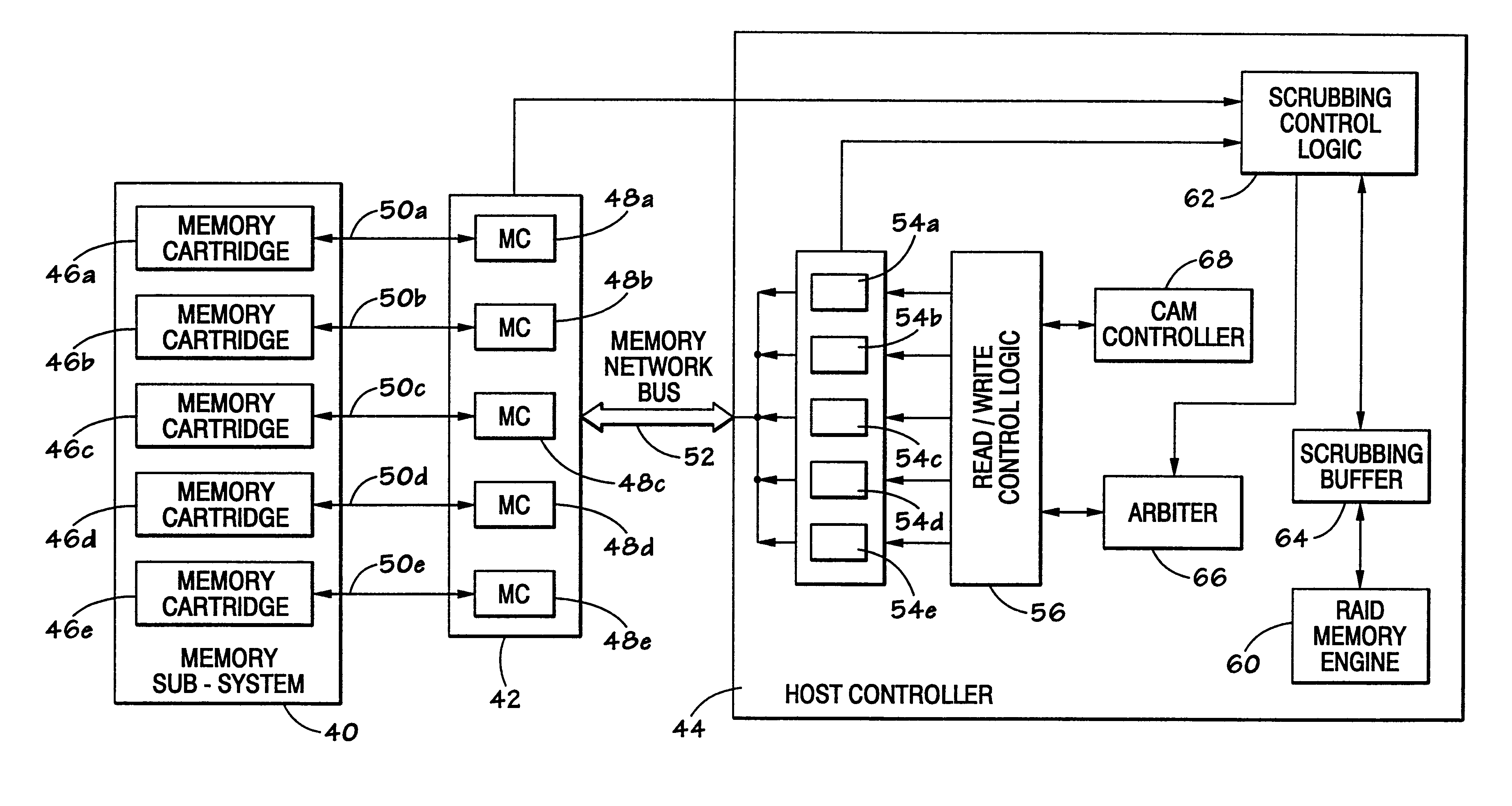
A system and technique for correcting data errors in a memory device. More specifically, data errors in a memory device are corrected by scrubbing the corrupted memory device. Generally, a host controller delivers a READ command to a memory controller. The memory controller receives the request and retrieves the data from a memory sub-system. The data is delivered to the host controller. If an error is detected, a scrub command is induced through the memory controller to rewrite the corrected data through the memory sub-system. Once a scrub command is induced, an arbiter schedules the scrub in the queue. Because a significant amount of time can occur before initial read in the scrub write back to the memory, an additional controller may be used to compare all subsequent READ and WRITE commands to those scrubs scheduled in the queue. If a memory location is rewritten with new data prior to scheduled scrub corresponding to the same address location, the controller will cancel the scrub to that particular memory location.

Description

1. Field of the InventionThe present invention relates generally to memory protection and, more specifically, to a technique for detecting and correcting errors in a memory device.2. Description of the Related ArtThis section is intended to introduce the reader to various aspects of art which may be related to various aspects of the present invention which are described and / or claimed below. This discussion is believed to be helpful in providing the reader with background information to facilitate a better understanding of the various aspects of the present invention. Accordingly, it should be understood that these statements are to be read in this light, and not as admissions of prior art.Semiconductor memory devices used in computer systems, such as dynamic random access memory (DRAM) devices, generally comprise a large number of capacitors which store the binary data in each memory device in the form of a charge. These capacitors are inherently susceptible to errors. As memory de...

Claims


Application Information

Patent Timeline
Patent Type & Authority Patents(United States)
IPC IPC(8): G06F11/00G06F11/30
CPCG06F11/106G06F11/1076G06F2211/1088
Inventor LARSON, JOHN E.MACLAREN, JOHN M.LESTER, ROBERT A.PICCIRILLO, GARY J.JOHNSON, JEROME J.FERGUSON, PATRICK L.
Owner SK HYNIX INC
Learn More