Flat display panel with a front protection plate

Inactive Publication Date: 2004-12-21
ASAHI GLASS CO LTD
View PDF18 Cites 46 Cited by
  • Summary
  • Abstract
  • Description
  • Claims
  • Application Information

AI Technical Summary

Problems solved by technology

However, among the above-described prior arts, in (A), since an electrically conductive mesh is used as the electromagnetic wave shielding material, if the numerical aperture of the mesh is lowered to increase the electromagnetic wave shielding property, the mesh tends to shield light emitted from the PDP main body, whereby the light transmittance tends to decrease, and the clarity of the image may be impaired, and if the numerical aperture of the mesh is increased, although the light transmittance improves, the electromagnetic wave shielding property tends to deteriorate.
For example, in the construction as disclosed in JP-A-11-119666, if a near infrared ray shielding layer employing a near infrared ray absorbent is provided instead of the heat radiation cutting film empl

Method used


Image

  • Flat display panel with a front protection plate
  • Flat display panel with a front protection plate

Examples


example 2

PDP was prepared in the same manner as in Example 1 except that the thickness of the soda lime glass was 2.5 mm, and the breaking test was carried out. The stress was 6.5 MPa and the distortion was 3 mm when the PDP was broken.

example 3

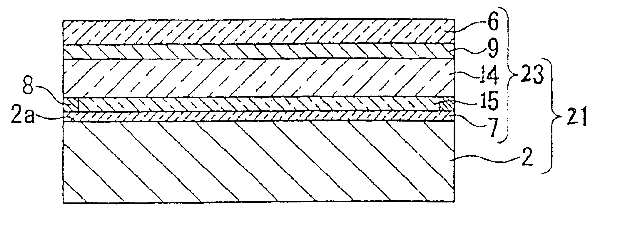
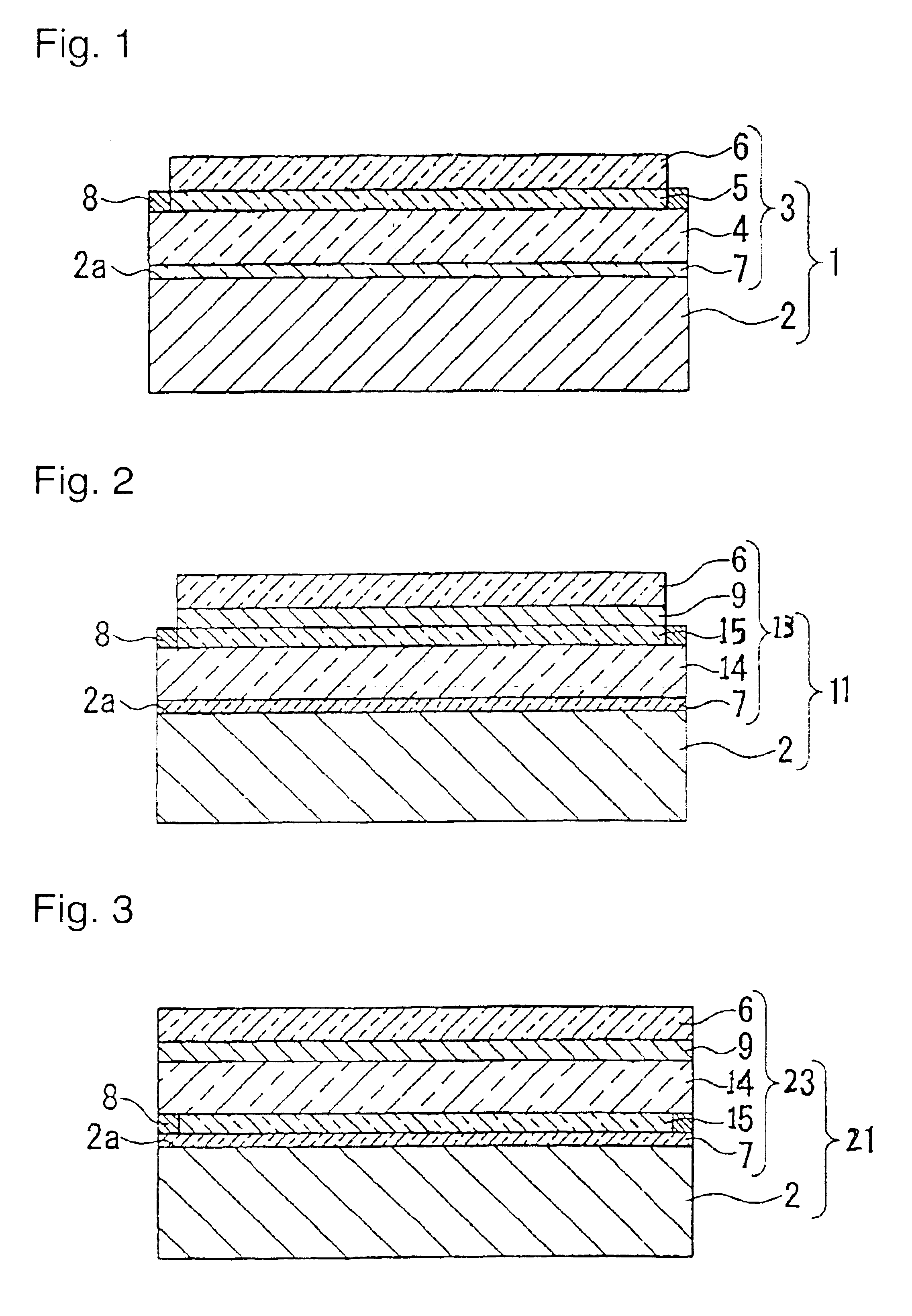
A front protective plate having a film by sputtering formed thereon and an antireflection film bonded thereto was obtained in the same manner as in Example 1 except that the thickness of the soda lime glass plate was 2.5 mm.

This front protective plate and a PDP main body were bonded and integrated by mans of an adhesive layer by the following method.

100 Parts by mass of a silicone resin solution ("SE1885A", tradename, manufactured by Dow Corning Toray Silicone Co., Ltd.) and 100 parts by mass of a curing agent for silicone resin ("SE1885B", tradename, manufactured by Dow Corning Toray Silicone Co., Ltd.) were mixed, and the side of the front protective plate where the antireflection film was not bonded, was coated with the above mixture in a thickness of 0.5 mm by means of a bar coater, followed by annealing treatment at 100.degree. C. for 30 minutes to prepare a front protective plate having an adhesive layer comprising a silicone resin formed thereon.

This front protective plate wa...

example 4

An integrated product of a front protective plate and a PDP main body was obtained in the same manner as in Example 3 except that the following polyurethane film adhesive layer was employed instead of the adhesive layer comprising the silicone resin. The breaking test was carried out in the same manner as in Example 1, and the stress was 9.0 MPa and the distortion was 2.6 mm when the PDP was broken.

65 Parts by mass of Preminol PML-3012 (tradename, polyether type polyol manufactured by Asahi Glass Company, Limited), 28 parts by mass of Excenol EL-1030 (tradename, polyether type polyol manufactured by Asahi Glass Company, Limited), 100 parts by mass of Preminol PML-1003 (tradename, polyether type polyol manufactured by Asahi Glass Company, Limited), 30 parts by mass of hexamethylene diisocyanate, 0.2 part by mass of dibutyltin dilaurate and 2 parts by mass of an antioxidant ("IRGANOX 1010", tradename, manufactured by Ciba-Geigy) were mixed, followed by deaeration, and cast on a polyet...


PUM


Abstract

A flat display panel comprising a flat display panel main body, and a front protective plate which comprises an antireflection layer, a translucent electrically conductive layer, containing a metal having an electromagnetic wave shielding property and a near infrared ray shielding property, a highly rigid transparent substrate made of a tempered glass or a semi-tempered glass and an adhesive layer laminated in this order, bonded to the viewer's side surface of the flat display panel main body by means of the adhesive layer.

Description

BACKGROUND OF INVENTION1. Field of InventionThe present invention relates to a flat display panel having such a structure that a front protective plate is unitedly bonded to the viewer's side surface of a flat display panel main body so as to improve mechanical strength of the flat display panel particularly plasma display panel (hereinafter referred to simply as PDP) main body to prevent breakage, and to decrease electromagnetic noises and near infrared rays generated from the flat display panel main body.2. Discussion of the Background ArtIn recent years, PDP having such advantages that a large screen panel can be prepared and clear full color display can be given, has attracted attention. PDP is to provide a full color display in such a manner that a phosphor is selectively discharged to emit light in a large number of discharge cells isolatedly formed between two glass plates. From this principle of emission, electromagnetic waves and heat radiation (near infrared rays) to be a ...

Claims


Application Information

Patent Timeline
IPC IPC(8): H01J17/02H01J17/16
CPCH01J11/10H01J11/44H01J2329/892H01J2329/86H01J2329/869H01J2211/446B32B7/02G02B1/10
Inventor WACHI, HIROSHIMORIWAKI, KENMIYAKO, TAKEOMI
Owner ASAHI GLASS CO LTD
Why Eureka
Try Eureka