Gravity gradiometry

a gravity gradiometry and gravity technology, applied in the field of gravity gradiometry, can solve problems such as the introduction of higher frequency disturbances

Inactive Publication Date: 2005-01-04
GEDEX
View PDF24 Cites 75 Cited by
  • Summary
  • Abstract
  • Description
  • Claims
  • Application Information

AI Technical Summary

Benefits of technology

The vehicle disturbances can be quantified by measuring the attendant accelerations, whether those associated with displacements of the vehicle from its ideal path or those associated with internal vibrations of the vehicle components. It has been recognised by the inventors herein that the accelerations imparted to an aircraft or other mobile vehicle during normal operations can, through the system design, be separated into relatively distinct regimes within the frequency domain. The invention provides for an actively controlled isolation system between the vehicle and the gravity gradiometer that can be tailored according to frequency regime and different gravity gradiometer response characteristics, and to different environments (cabin restrictions and vehicle accelerations will be specific to different vehicles). The invention provides for a two-stage (coarse and fine stage) isolation system that effectively separates accelerations into two frequency regimes. The first isolation stage or mount attenuates accelerations (and resulting translations) particularly those of low frequency. This stage provides relatively large displacement movements of the gravity gradiometer relative to the aircraft structure through operation of a Coarse Isolation Mount (CIM). The CIM limits the relative displacement with a weak restoring force such that the probability of a payload (e.g., a gravity gradiometer) reaching the physical limits of the system (i.e., the vehicle cabin) in normal operation is small. The CIM will have its own dynamics and will inevitably introduce some higher frequency disturbances. The second isolation stage is mounted to (or nested within) the first isolation stage, and reduces linear accelerations in all three axis, particularly of high frequency, including some which can be transmitted through and amplified by the CIM dynamics. This second isolation stage also provides rotational isolation about all three axis.
The result of this system is that gravity gradient signals measured by the gravity gradiometer are relatively free of noise produced by translational as well as rotational vehicle accelerations, and provide previously unobtainable resolution and accuracy.

Problems solved by technology

The CIM will have its own dynamics and will inevitably introduce some higher frequency disturbances.

Method used


Image

  • Gravity gradiometry
  • Gravity gradiometry
  • Gravity gradiometry

Examples


Embodiment Construction

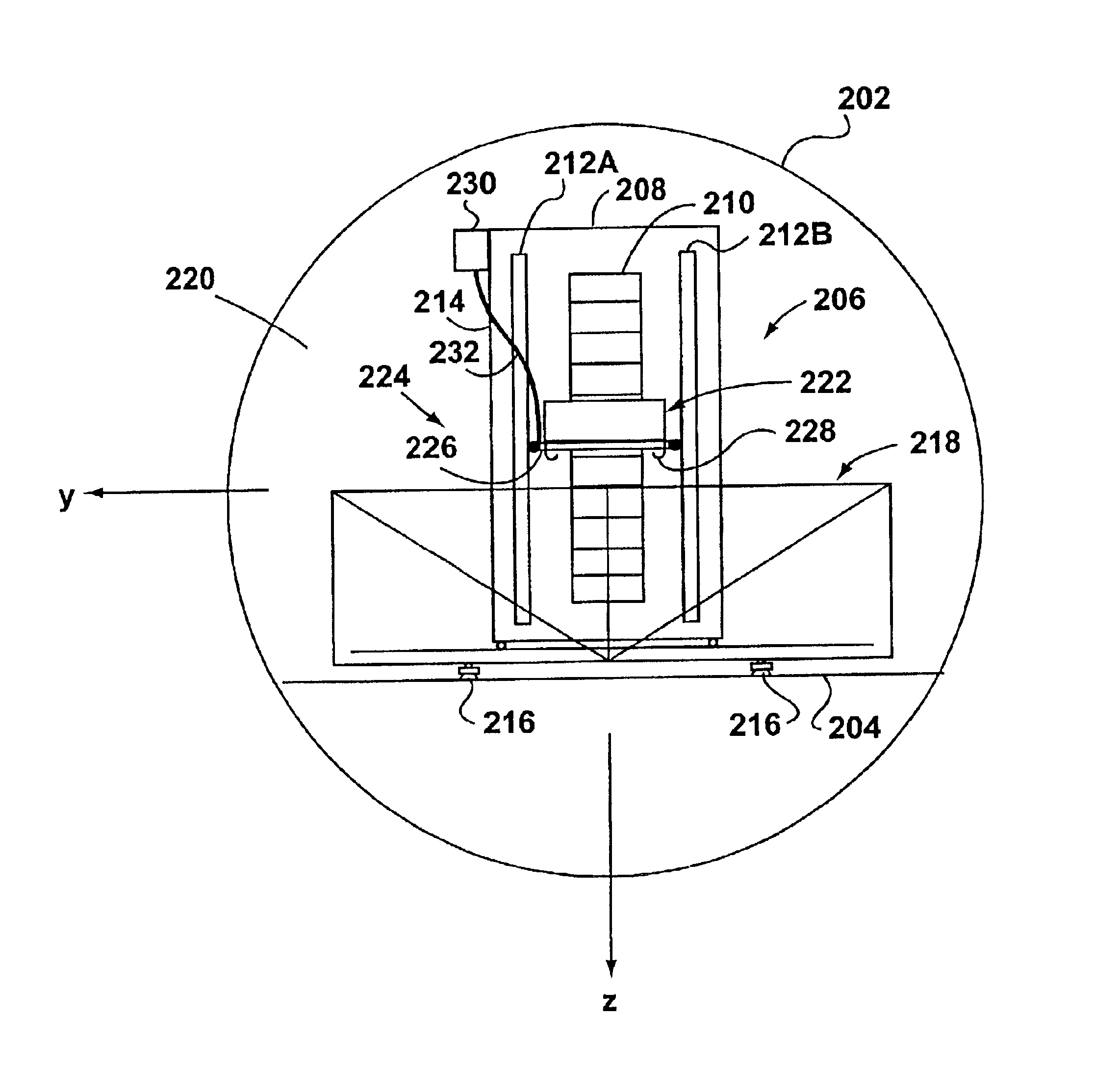
Referencing FIG. 7, the inventors have noted that, ideally, the center of mass of each dumbbell 1102 in a crossed dumbbell gravity gradiometer will be exactly coincident with its center of rotation. This rotation occurs about a pivot, which can conveniently be in the form of a web connecting the dumbbell to the instrument body. In this case the web also acts as a torsion spring. Such a structure is described in U.S. Pat. Nos. 5,804,722, 5,505,555 and 5,668,315 issued to Van Kann.

The elegance of this concept lies in its ability, at least ideally, to discriminate against translational and angular accelerations. With the center-of-mass of each bar 1102 coincident with its center of rotation, except for second order effects described below, no net torques are produced by translational accelerations, so no scissoring rotations occur due to translational accelerations.

For the effect of translational accelerations, it has been noted by the inventors that all real instruments depart from th...


PUM

PropertyMeasurementUnit
frequenciesaaaaaaaaaa
gravitational accelerationaaaaaaaaaa
accelerationaaaaaaaaaa

Abstract

A gravity gradiometer is combined with a two-stage actively controlled isolation system. The gravity gradiometer and two stage isolation system may then be mounted within (or on) a mobile vehicle such as, for example, an aircraft. It has been recognized by the inventors herein that the accelerations imparted to an aircraft during normal operations can be separated through system design into two relatively distinct regimes within the frequency domain. The invention provides a first isolation mount, which forms part of the isolation system, to isolate accelerations (and resulting translations) falling within a first of the two frequency regimes. The second isolation mount, which is mounted to the first isolation mount, isolates accelerations falling within the second of the two frequency regimes. A gravity gradiometer can then be mounted to the second isolation mount. As a result of housing the gravity gradiometer within the nested isolation system (a combination of the first and second isolation mounts), the gravity gradiometer is substantially isolated from the accelerations experienced by the mobile vehicle. Consequently, gravity gradients measured by the gravity gradiometer are relatively noise free and provide heretofore-unobtainable accuracy.

Description

FIELD OF THE INVENTIONThe present invention relates to an apparatus, method and system for measuring gravitational acceleration and the gradient in the gravitational acceleration (termed the gravity gradient) and, in particular, to an apparatus, method and system for the exploration and measurement of the local variations in the gravitational field of bodies such as the earth.BACKGROUND TO THE INVENTIONThe strength of a local gravitational field depends upon the proximity to the mass of an object(s). The mass of an object, in turn, is dependent upon the density of the material of the object and the volume of the object. Accordingly, density variations of geological structures such as mineral deposits, oil reservoirs, underground tunnels or caverns have specific gravity signatures. These signatures, if measured with sufficient accuracy, can be used to assist in the identification of the corresponding geological structures.Accordingly, although for most purposes the gravitational acce...

Claims


Application Information

Patent Timeline
Patent Type & Authority Patents(United States)
IPC IPC(8): G01V7/00G01V7/16G01V1/00
CPCG01V7/16G01N7/16
Inventor ETKIN, BERNARDFRENCH, JOHN BARRYTRYGGVASON, BJARNI V.VAN KANN, FRANK J.
Owner GEDEX
Why Eureka
Try Eureka