Apparatus and method for filling cavities with metered amounts of granular particles

a technology of granular particles and apparatus, which is applied in the direction of liquid handling, packaging goods, transportation and packaging, etc., can solve the problems of increasing the cost of the system, difficult to achieve 100 percent filling of the cavities in the article, and difficulty in achieving consistent accurate filling of the desired cavities with granular particles, etc., to achieve the effect of accurate filling and faster transfer of particles

Inactive Publication Date: 2005-01-04
PHILIP MORRIS USA INC
View PDF14 Cites 78 Cited by
  • Summary
  • Abstract
  • Description
  • Claims
  • Application Information

AI Technical Summary

Benefits of technology

The filling system adjacent to the rotating wheel includes a vertical drop chute with a height that is determined such that the particles accelerate under gravity through the drop chute and are traveling at approximately the surface speed of the rotating wheel when the particles enter the filling chamber. The filling chamber includes openings at the top to receive the particles from the vertical drop chute, at the bottom so that excess particles can drop out of the bottom of the filling chamber to be captured and recycled, and on the side of the filling chamber facing the rotating wheel. The side of the filling chamber opposite from the rotating wheel is provided with air inlets to allow cross air flow through the filling chamber and into the pockets of the rotating wheel. The filling chamber can also be provided with optional deflector vanes to assist in deflecting the particles into the wheel pockets. As particles enter the top of the filling chamber from the vertical drop chute, cross air flow produced by the wheel vacuum and the inlets in the side of the filling chamber opposite from the wheel, direct the particles toward the wheel. The vacuum created by the stationary internal vacuum plenum pulls the particles into the wheel pockets until the pockets are full. A scraper can be provided at the bottom of the filling chamber to scrap the outer surface of the wheel, thereby ensuring that each wheel pocket is accurately filled. A stationary air jet can also be provided inside the rotating wheel at a position adjacent the end of the vacuum plenum in the direction of rotation of the rotating wheel. The air jet directs a blast of air radially outwardly to assist in rapidly emptying each pocket of the rotating wheel as it rotates past the end of the vacuum plenum.
The cavities to be filled with the granules or particles are passed underneath the rotating wheel and their movement is synchronized with the movement of the rotating wheel so that each cavity to be filled coincides with a pocket on the outer surface of the rotating wheel. A vacuum rail for conveying the article or articles having the cavities to be filled can also be provided. The material in which the cavities are formed can be a porous material that allows the vacuum from the vacuum rail to create a negative pressure in the cavities. An example of such a porous material is the paper used in forming cigarette filter rods. The vacuum rail can also be provided with separate chambers having higher and lower amounts of vacuum such that a chamber having the higher vacuum coincides with the cavity that is being filled with particles from the rotating wheel, while the other areas of the article coincide with the chambers having lower vacuum. The use of a high vacuum section in the vacuum rail at the point of particle transfer, and low vacuum at other points allows for quicker transfer of particles at the transfer point without having to adjust the rate at which the cavities are moved underneath the rotating wheel.
The pockets in the outer surface of the rotating wheel diverge radially inwardly, thus getting wider at the bottom of each pocket, in order to resist the effects of centrifugal force created by the rotation of the wheel and to allow a deeper pocket depth to hold more particles. The use of only one wheel to both meter the particles and transfer the particles to cavities in an article overcomes a problem in the prior art wherein progressively larger pockets are required for metering and transfer of particles with more than one wheel. The use of a single wheel allows use of a larger pocket size to achieve 100 percent fill of the cavities in an article.

Problems solved by technology

During high speed mass production of such articles it is difficult to achieve consistent accurate filling of the desired cavities with the granular particles.
This arrangement makes it difficult to achieve 100 percent fill of the cavities in the article receiving particulate material from the transfer wheel.
The provision of discrete screens at the base of each conical bore creates assembly problems and increases the expense of the system taught by the '824 patent.
The individual screens can also restrict airflow into the pockets to an undesirable extent.

Method used


Image

  • Apparatus and method for filling cavities with metered amounts of granular particles
  • Apparatus and method for filling cavities with metered amounts of granular particles
  • Apparatus and method for filling cavities with metered amounts of granular particles

Examples


Embodiment Construction

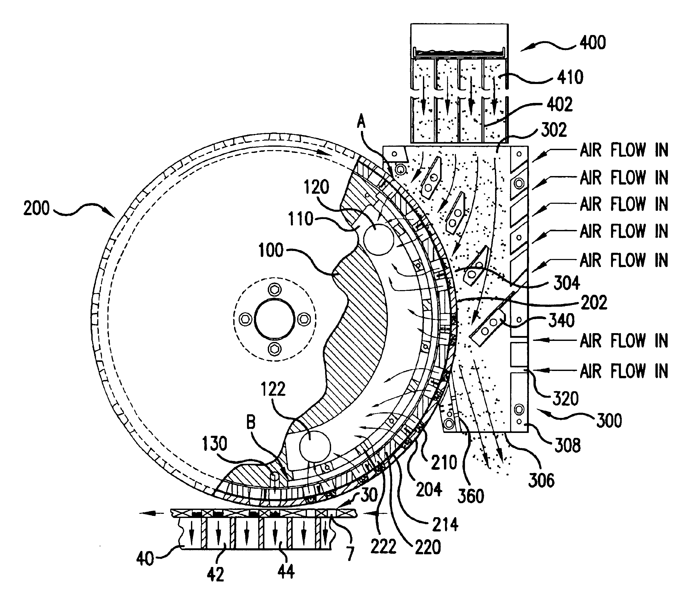
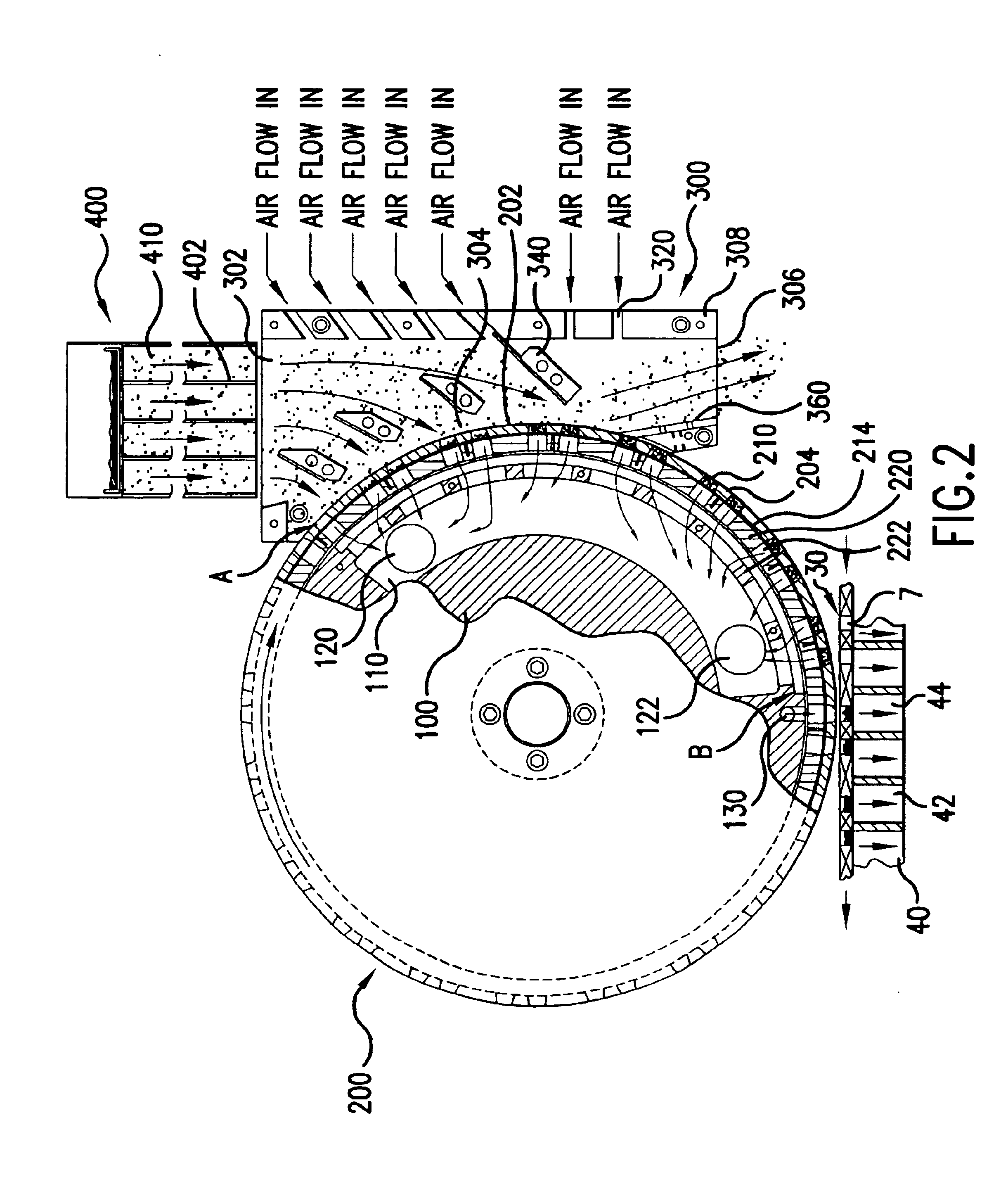
The invention provides a system useful for transferring accurately metered volumes of particles to cavities in an article or articles being produced at a high rate during mass production. The system includes a single wheel that rotates around a central stationary drum defining at least one vacuum chamber. A series of pockets are defined along an outer circumferential surface of the rotating wheel between the outer periphery of the wheel and a perforated band or screen that is clamped against the inner periphery of the wheel, to both accurately meter and transfer predetermined amounts of granules or particles into cavities of one or more articles. Accurate metering and transfer of particles is achieved through the use of a combination of features that include a filling system that uses gravitational acceleration of the particles and cross air flow to achieve rapid filling of the pockets in the rotating vacuum wheel, and a vacuum rail for transporting the article or articles that is u...


PUM

PropertyMeasurementUnit
velocityaaaaaaaaaa
distanceaaaaaaaaaa
vacuumaaaaaaaaaa

Abstract

A method and apparatus for delivering predetermined amounts of material, the apparatus including a vertical drop chute, a filling chamber, a rotating wheel with pockets, a central stationary drum with at least one vacuum chamber and an air jet, and a vacuum rail for transporting an article underneath the rotating wheel and transferring the particles from pockets in the wheel to cavities in the article. The particles can be carbon or charcoal granules and the article can be a cigarette filter rod.

Description

FIELD OF THE INVENTIONThe present invention relates generally to methods and apparatus for accurately delivering precisely metered amounts of particulate material repetitively during high speed manufacture of particulate-filled articles of manufacture, and most particularly, to precise, repetitive delivery of granular charcoal in spaces presented during the manufacture of plug-space-plug cigarette filters.BACKGROUND OF THE INVENTIONCertain articles of manufacture such as charcoal cigarette filters, individual-sized packets of granular food products or condiments, capsuled pharmaceuticals, ammunition and the like require repetitive placement of precisely metered charges of particulate matter at some location along the production-line procession of the articles. During high speed mass production of such articles it is difficult to achieve consistent accurate filling of the desired cavities with the granular particles. In the case of filling cigarette filter cavities with charcoal, it ...

Claims


Application Information

Patent Timeline
Patent Type & Authority Patents(United States)
IPC IPC(8): B65B1/30B65B1/36
CPCB65B1/366
Inventor SPIERS, STEVEN F.GARTHAFFNER, MARTIN F.ATWELL, GARY
Owner PHILIP MORRIS USA INC
Why Eureka
Try Eureka