Check valve, fan unit, and forced air cooling system

a technology of fan unit and check valve, which is applied in the direction of cooling/ventilation/heating modifications, electrical apparatus casing/cabinet/drawer, lighting and heating apparatus, etc., can solve the problems of inability to use, low efficiency, and high price of valve type, so as to reduce the impedance of air flow

Inactive Publication Date: 2005-01-04
TELEFON AB LM ERICSSON (PUBL)
View PDF6 Cites 42 Cited by
  • Summary
  • Abstract
  • Description
  • Claims
  • Application Information

AI Technical Summary

Benefits of technology

The vanes of the valve may be associated with stops positioned so that all of the vanes will be essentially parallel in their open positions. However, in an alternative embodiment the stop for a first vane is positioned further from the balanced position than the stops for the remaining vanes. Expressed otherwise, the first vane in its open position forms a larger angle with the general direction of fluid flow through the valve, than the remaining valves. Accordingly, said first vane will close first in the event of fan failure, and will during its closing movement engage the adjacent vane and create what may be referred to as a “domino-effect” securing a distinct closing action.
In another embodiment the “domino-effect” may be optimized for secure closing of the valve.

Problems solved by technology

This type of valve is therefore comparatively expensive and not suitable for use in applications requiring only a simple inexpensive device for preventing back-flow.
Thereby, the vanes offer considerable resistance to said airflow and cause a pressure drop across the back-flow preventing valve.
Even with such attempts, the blades still cause a pressure drop that may be unacceptable in certain applications.
Lowering the weight of the blades may also cause vibration and resulting noise and a special design for the blades wi

Method used


Image

  • Check valve, fan unit, and forced air cooling system
  • Check valve, fan unit, and forced air cooling system
  • Check valve, fan unit, and forced air cooling system

Examples


first embodiment

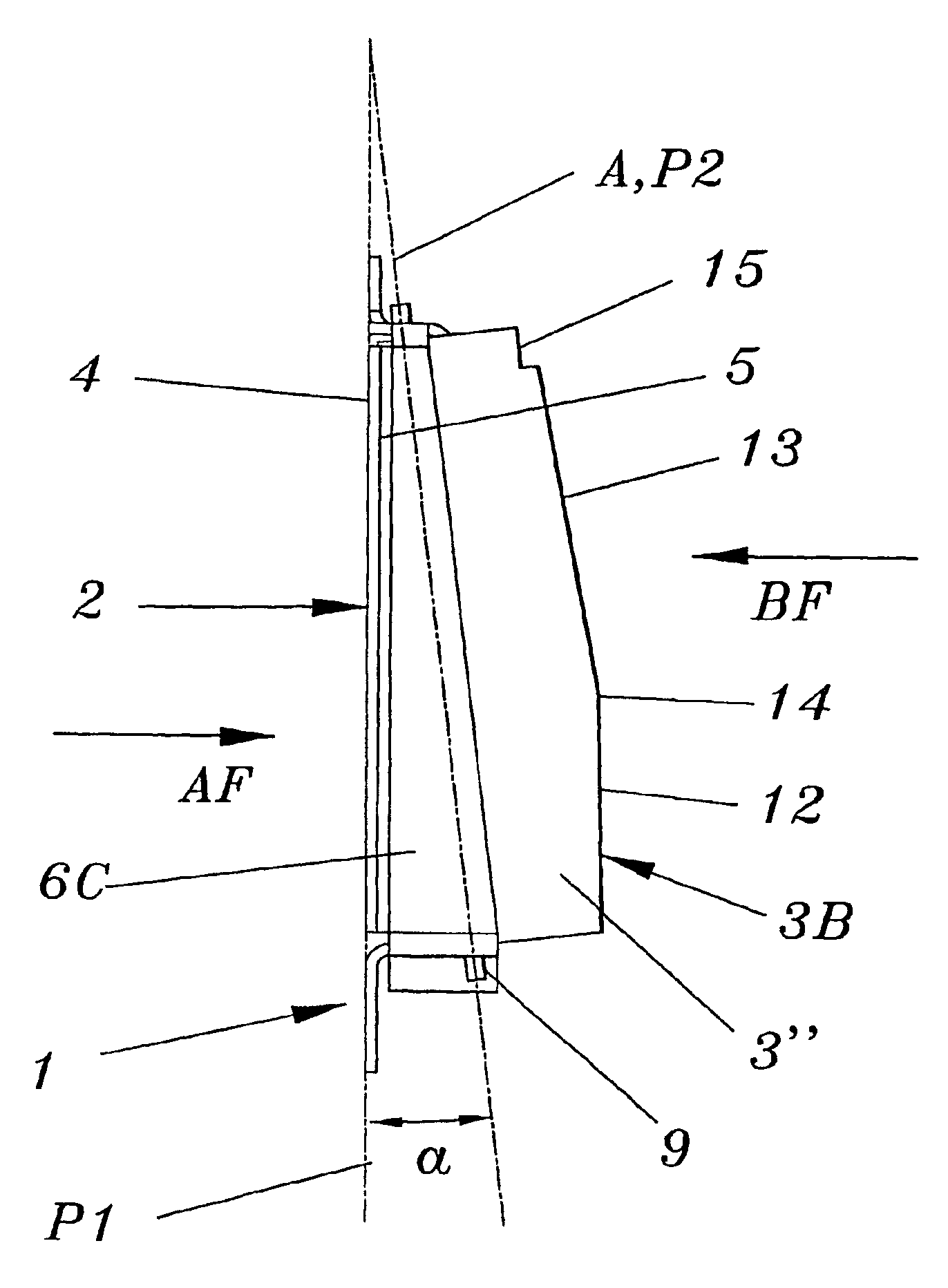
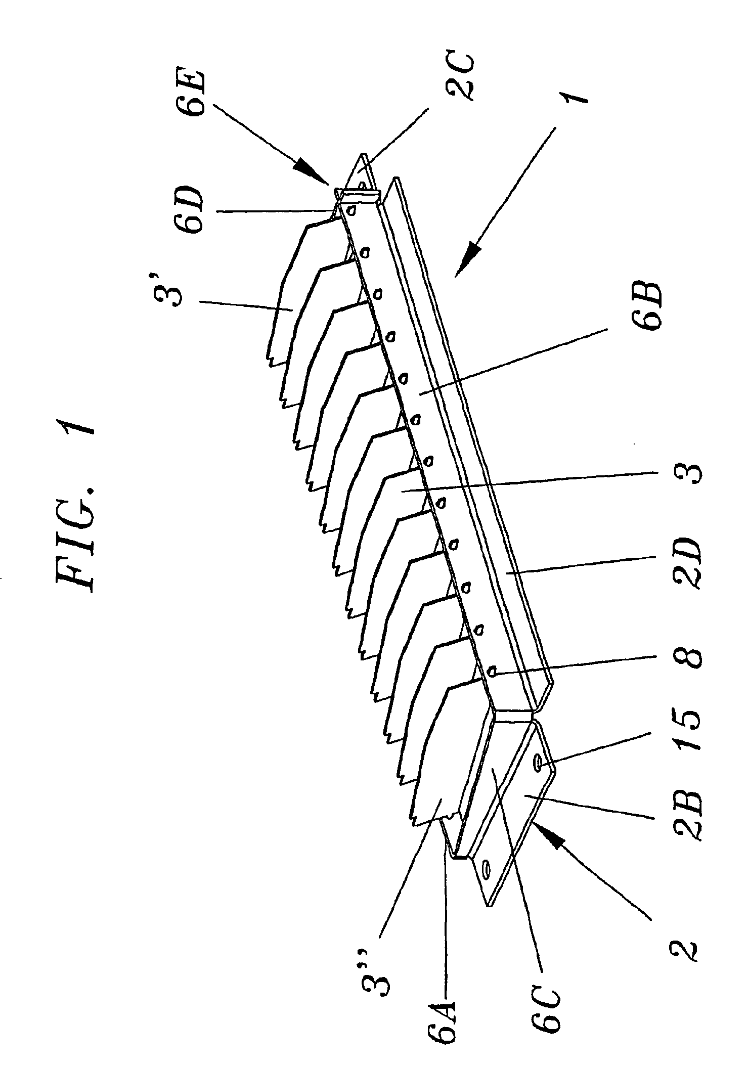
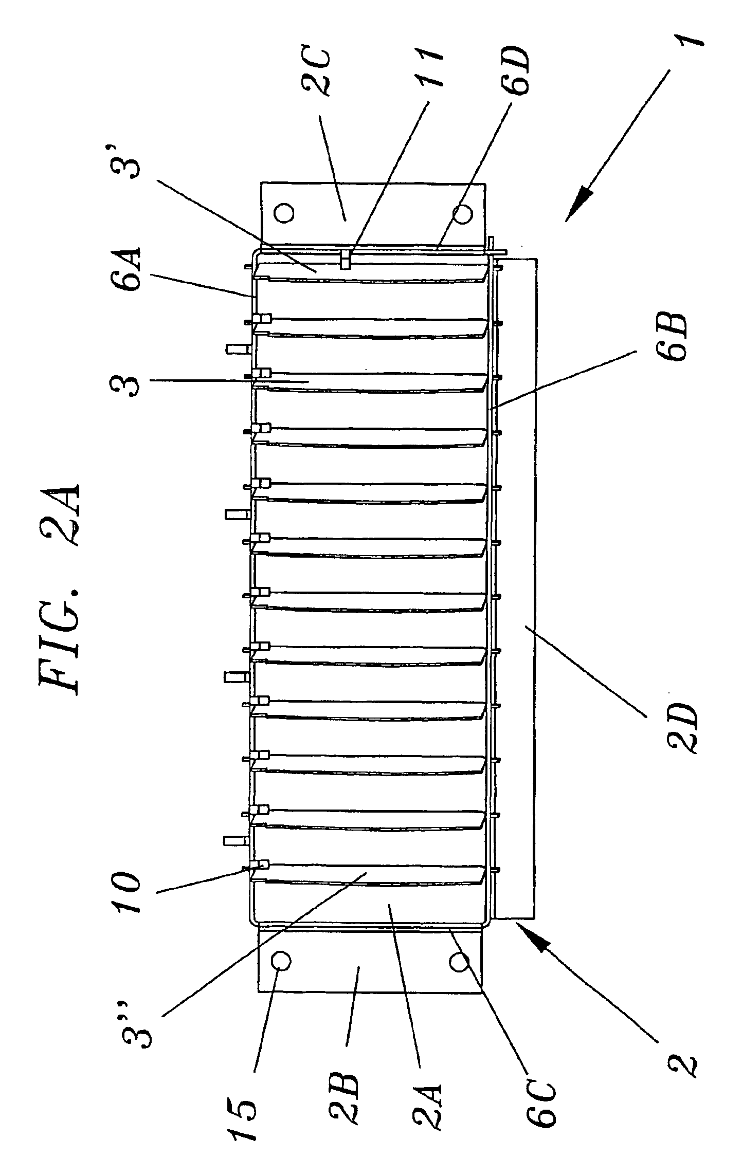
the invention will now be described with specific reference to drawing FIGS. 1-6. Basically, the valve assembly 1 of the invention consists of a generally rectangular frame 2 in which a number of valve vanes 3, 3′, 3″ are pivotally supported, as is best illustrated in FIGS. 1 and 2B. Like in the conventional valves the vanes are pivotal about pivot axes A that are extended generally transversal to the general direction of flow AF (see FIG. 2B) through the valve. The frame 2 has flanges 2B-D likewise extending transversal to the general direction of flow AF and serving to support the valve 1 on a vertical wall 34 of a fan unit 30 casing 31, as will be described more closely below with reference to FIG. 10. For that purpose two of the flanges 2B, 2C are provided with bores 15 for fasteners 16 (see FIG. 10), such as bolts.

The rear side 4 of the frame 2, in effect being the rear side of said flanges 2B-D, is flat and forms a base plane P1 of the valve 1. For the purpose of this descript...

third embodiments

Modified, second and third embodiments of the inventive valve assembly 50, 100 will now be described with reference to FIGS. 7 and 8 that show said embodiments in views corresponding to that of FIG. 5 in order to specifically illustrate the open position angles β, β′ of the vanes 3, 3′, 3″. The valves 50, 100 of FIGS. 7 and 8 are identical to that of the first embodiment, except for the orientation of the vanes in the open position OP. Regarding the different parts of the valves 50, 100 bearing the same reference numerals as in the first embodiment, reference is made to the above description thereof.

In the second embodiment of FIG. 7 the open position angle β′ of the first vane 3′ is chosen to be the same as the angles β, β′ of the first embodiment, i.e. approximately 16°. On the other hand, the open position angle β of the remaining vanes 3, 3″ is chosen to be significantly smaller, in the illustration approximately 10°. Choosing this smaller angle of the vanes even further reduces...


PUM


Abstract

A backflow preventing check valve for use in a fan unit in a forced air cooling system includes a generally rectangular frame, a plurality of adjacent parallel pivot axes mounted in the frame, and a plurality of adjacent vanes that pivot around the axes between open and closed positions. The axes extend generally transverse to the direction of fluid flow through the valve, and each axis is offset from the center of gravity of its associated vane so that fluid flowing through the valve in an allowed direction moves the vanes toward the open position, and fluid flowing in a blocked direction moves the vanes toward the closed position. The axes are inclined at an angle (α) measured from a vertical reference, thereby causing the vanes to be urged by gravity to pivot towards the closed position.

Description

TECHNICAL FIELDThe present invention relates generally to devices that are employed for allowing full or regulated fluid flow in one specified direction when in their open condition and for preventing fluid flow in the opposite direction when in their closed condition, such devices being generally referred to as check valves.BACKGROUNDCheck valves are very common in various applications for controlling the flow of gaseous or liquid fluids in the above described manner. With regard to the operation of the valves between their fully or partly open and closed conditions, such check valves are normally of one of three major types. Specifically, the check valves may be operated between their different positions by a control means acting directly or indirectly upon a valve member for regulating the flow through the valve. This type of valve also includes manual operation of the control means or the valve member. It is mostly used in pneumatic and hydraulic fluid systems requiring a relati...

Claims


Application Information

Patent Timeline
IPC IPC(8): H05K7/20
CPCH05K7/20181
Inventor SODERLUND, PER THOMAS
Owner TELEFON AB LM ERICSSON (PUBL)
Why Eureka
Try Eureka