Fire assembly for recessed electrical fixtures

a technology for fire assembly and electrical fixtures, which is applied in the direction of electrical apparatus casings/cabinets/drawers, lighting and heating apparatus, lighting support devices, etc., can solve the problems of changing the fire safety requirements of the assembly, the floor-ceiling assembly may no longer meet certain fire safety standards, and the non-continuous surface, etc., to achieve the effect of convenient connection

Inactive Publication Date: 2005-01-04
HUBBELL INC
View PDF51 Cites 92 Cited by
  • Summary
  • Abstract
  • Description
  • Claims
  • Application Information

AI Technical Summary

Benefits of technology

In some embodiments, a fire assembly of the present invention can also include a junction box for wiring the recessed light fixture. For instance, in one embodiment, the junction box can be contained within the housing. Moreover, in another embodiment, the junction box can be positioned outside the housing on a portion of the bottom wall of the housing extending beyond the intersection of the bottom wall and one of the side walls. Regardless of the position of the junction box, at least one conduit can be provided that can extend from the junction box to another conduit of another fire assembly or recessed light fixture. Consequently, such a conduit(s) can allow a fire assembly of the present invention to be easily connected to various other light fixtures within a building structure.

Problems solved by technology

However, one problem associated with installing recessed electrical fixtures in such a manner is that the hole cut in the surface can change the fire safety requirements of the assembly.
By cutting a hole in the ceiling, a non-continuous surface can result and the floor-ceiling assembly may no longer satisfy certain fire safety standards.
However, because these fire boxes are unattached and must be fabricated by the builder separately from the lighting fixture, a substantial amount of additional time and expense can be incurred.
Moreover, because most builders are unaware of what size box is required for fire safety, exceedingly large boxes have often been utilized, causing unneeded cost and expense.

Method used


Image

  • Fire assembly for recessed electrical fixtures
  • Fire assembly for recessed electrical fixtures
  • Fire assembly for recessed electrical fixtures

Examples


example

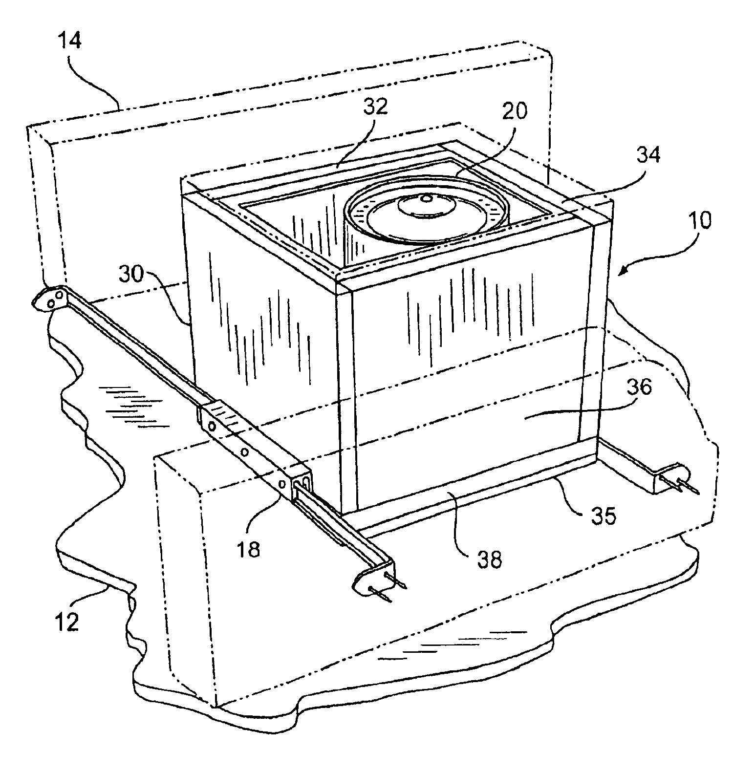
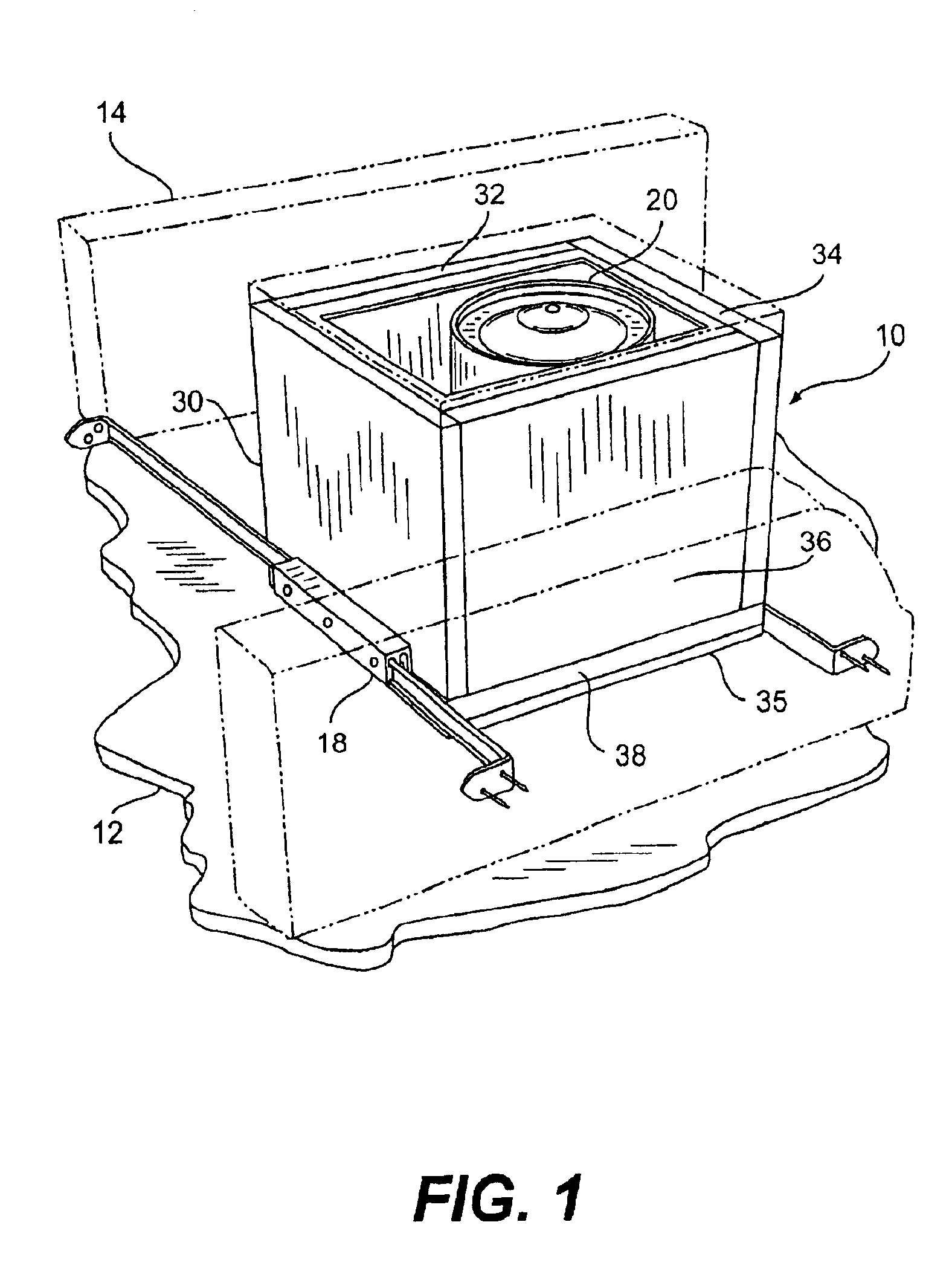
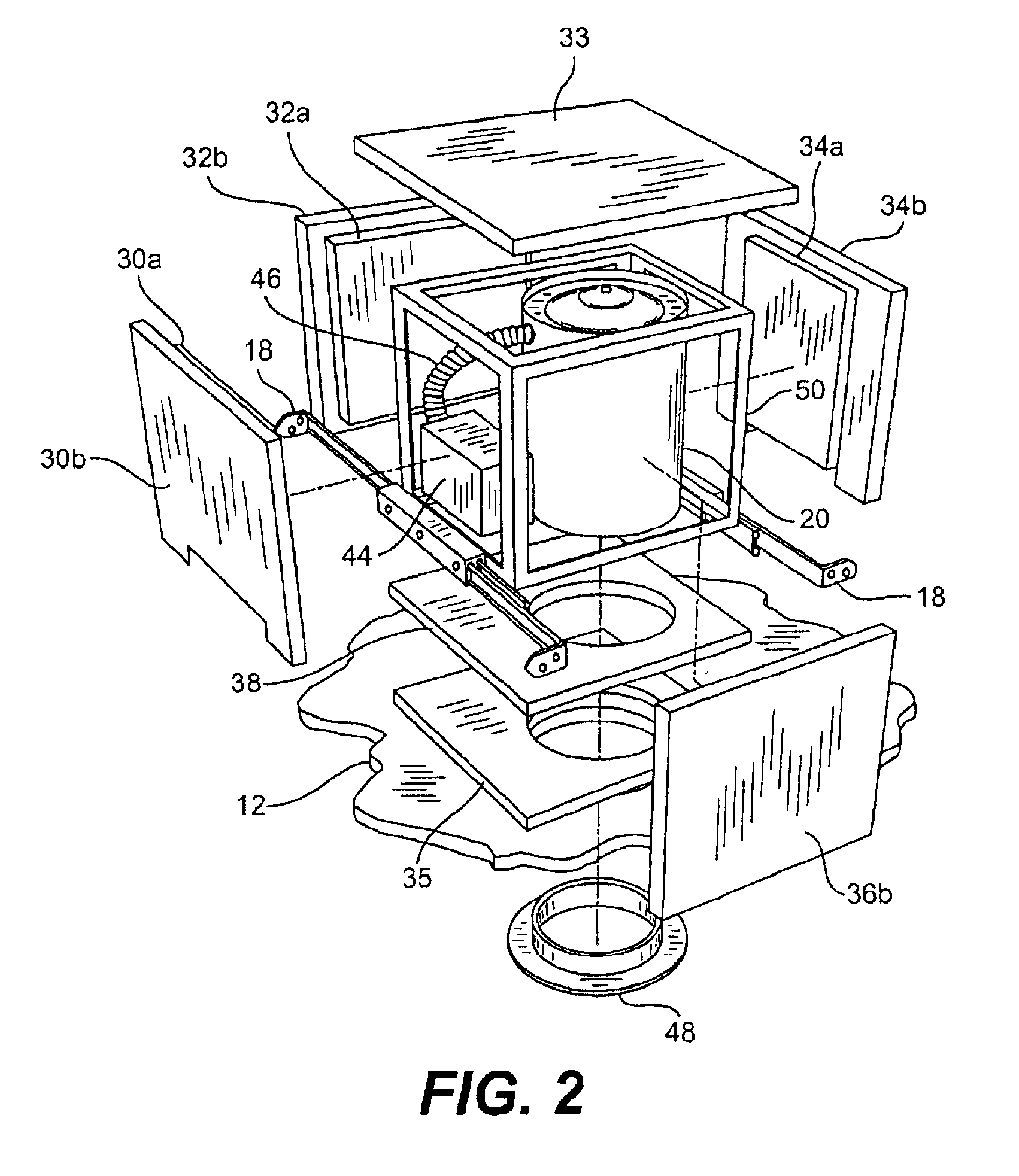
The ability of a fire assembly of the present invention to maintain the fire rating of a floor-ceiling assembly was demonstrated. Initially, a fire assembly was formed as described above. In particular, a cube-shaped housing was formed by attaching four side walls and a top wall. Each wall contained sheet rock as the generally fire resistant material. The cube-shaped housing was then attached to a metallic support structure. To complete the fire assembly, the support structure and housing were subsequently attached to an incandescent recessed lighting fixture to form the fire assembly.

Once formed, the fire assembly was then tested according to UL standards. In particular, a 48-inch by 48-inch small scale floor-ceiling assembly was constructed as described in Design No. L501, which is set forth in UL=s 1999 Fire Resistance Directory and illustrated in FIG. 6. As shown in FIG. 6, the fire assembly was installed in a joist cavity while an adjoining joist cavity remained unchanged. As a...


PUM


Abstract

A fire assembly that can be used for installing recessed electrical fixtures into various structures such as wall assemblies is provided. The fire assembly includes an electrical fixture contained within a generally fire-resistant housing. The housing can enclose the electrical fixture in such a manner that the resulting fire assembly has an integral structure. In some instances, a support structure can be utilized to attach the housing to the electrical fixture. Furthermore, the housing can be a cube-shaped box have a variety of generally fire-resistant walls. These walls can be made from materials such as sheet rock.

Description

FIELD OF THE INVENTIONThe present invention generally relates to a fire assembly that can be used to install recessed electrical fixtures into various structures.BACKGROUND OF THE INVENTIONCurrent residential buildings, such as apartments, assisted living housing developments, or condominiums, can be constructed in a variety of ways. Regardless of the manner of construction, however, the building must generally comply with certain fire safety standards, such as set forth by Underwriters Laboratories (“UL”). For example, wood joists and sheet rock are typically used to create a residential-like atmosphere. When using such materials, the building structure must typically satisfy a specific UL “fire-rated” assembly standard. For example, one applicable test is UL=s 1 hr. Fire Rated L-500 Floor-Ceiling Assembly test. This test measures and rates a given floor-ceiling assembly for fire safety compliance.Very often, it is desired to install various accessories into building structures. Fo...

Claims


Application Information

Patent Timeline
Patent Type & Authority Patents(United States)
IPC IPC(8): F21V25/00F21S8/02F21V15/00F21V15/06F21V29/15
CPCF21S8/02F21S8/026F21V25/12F21V25/00F21V29/15F21V21/048E04F19/08E04C2/52E04F19/00
Inventor NEWBOLD, RONALDWHITE, THOMAS T.
Owner HUBBELL INC
Why Eureka
Try Eureka