Particle beam processing system

a particle beam and processing system technology, applied in the field of particle beams, can solve the problems of not showing a way to actually make and use this idea, and the charge particle also endures collisions, so as to reduce the size of the overall beam processing system, reduce the dependence of the bending angle, and reduce the cost

Inactive Publication Date: 2005-01-04
HBAR TECH LC
View PDF4 Cites 177 Cited by
  • Summary
  • Abstract
  • Description
  • Claims
  • Application Information

AI Technical Summary

Benefits of technology

Another aspect of the present invention is the superimposing of a second magnetic field that steers the charged particle beam. The simultaneous bending and focusing of a charged particle beam reduces the size of the overall beam processing system, reduces costs, and reduces the dependence of the bending angle out of the system on the kinetic energy of the charged particles.

Problems solved by technology

Unfortunately, at the same time the charged particles also endure collisions with the nuclei within the material.
This idea is believed to be purely theoretical and no one has shown a way to actually make and use this idea.

Method used


Image

  • Particle beam processing system
  • Particle beam processing system
  • Particle beam processing system

Examples


Embodiment Construction

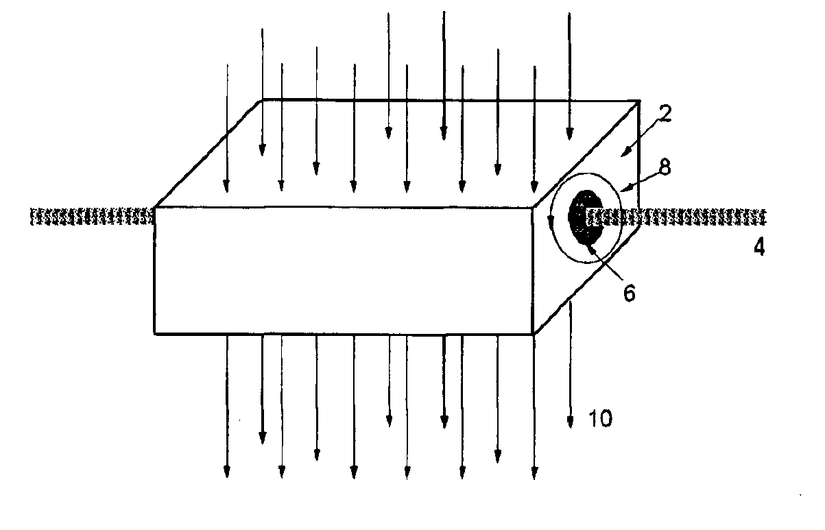
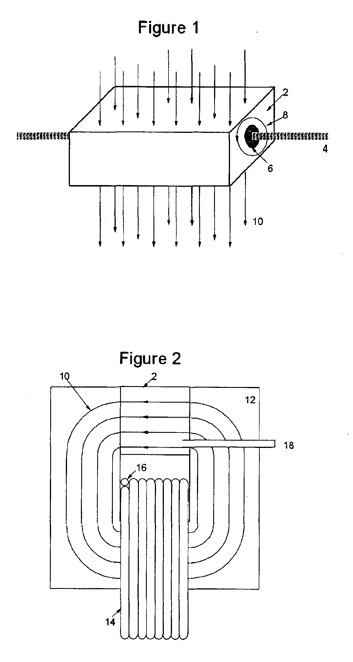
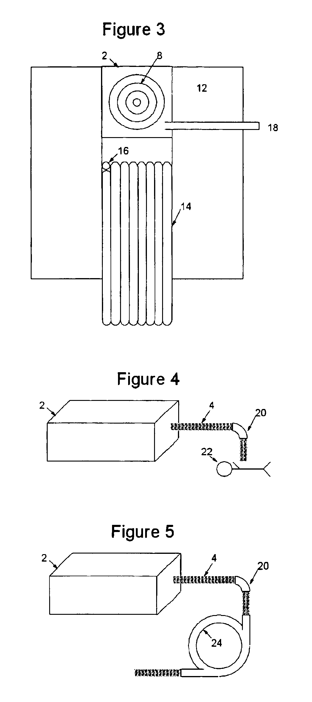
FIG. 1 is a schematic representation of the invention. In order to achieve a reduction in the kinetic energy of a charged particle beam 4, preferably antiprotons. The beam 4 is directed through a mass 2. This mass 2 can be composed of a variety of materials, and can be solid, liquid, gas, or a combination thereof. The mass 2 can have a solid shell to hold a liquid and / or gas. Steering of the beam 4 is accomplished by superimposing a bending magnetic field 10 through the material at a non-zero angle with respect to the trajectory of the charged particle beam 4.

The length and composition of the mass 2 is determined so as to rapidly decelerate the charged particle beam 4 to a desired output kinetic energy. The rate of deceleration can be higher than 100 MeV per centimeter by using solid uranium as the mass 2. Whereas traditional electromagnetic methods of accelerating and decelerating charged particle beams require significant power to create the electromagnetic fields, the mass 2 can ...


PUM


Abstract

A method for slowing and controlling a beam of charged particles includes the steps of superimposing at least one magnetic field on a mass and passing the beam through the mass and at least one magnetic field such that the beam and the mass slows but does not stop the particles. An apparatus for slowing and controlling a beam of charged particles includes a bending magnetic field superimposed on a focusing magnetic field within a mass.

Description

I. BACKGROUND OF THE INVENTIONA. Field of the InventionThis invention relates to the field of particle beams. More particularly, the present invention relates to the control of particle beams by modifying the size, divergence, direction, mean kinetic energy, and kinetic energy distribution of said particle beams. Even more specifically, the present invention addresses the extraction and deceleration of antiprotons from a synchrotron.B. Background of the InventionCharged particle beams are typically accelerated in linear accelerators, cyclotrons, or synchrotrons. It is often desirable to extract some or all of these charged particles and to transport them at a kinetic energy lower than the beam energy just prior to extraction. For example, a synchrotron can be used to decelerate a charged particle beam. One option pursued in synchrotrons has been to use a curved silicon crystal to guide the particles out of the accelerator and simultaneously lower the beam energy via collisions with ...

Claims


Application Information

Patent Timeline
Patent Type & Authority Patents(United States)
IPC IPC(8): G21K1/00G21K1/093H01J3/14H01J3/00H05H7/00H05H7/12G01Q60/00
CPCG21K1/093H05H7/12H01J3/14
Inventor JACKSON, GERALD P.
Owner HBAR TECH LC
Why Eureka
Try Eureka