Camera-based precrash detection system

a detection system and camera technology, applied in the field of camera-based precrash detection system, can solve the problems of limited range, inability to identify the other party, inability to reliably detect non-metallic objects (e.g., people or trees),

Inactive Publication Date: 2005-01-04
DAIMLER AG
View PDF25 Cites 158 Cited by
  • Summary
  • Abstract
  • Description
  • Claims
  • Application Information

AI Technical Summary

Benefits of technology

An object of the present invention is to devise a method and a suitable device which will make it possible to detect r

Problems solved by technology

The drawbacks of these systems are due, in part, to their limited range (ultrasound, infrared laser) and to their inability to identify the other party potentially involved in a collision, along the lines of a reliable type classification (truck, passenger car, motor cycle, person).
In radar-based systems, inter alia, non-metallic objects (e.g.: people or trees) are not

Method used


Image

  • Camera-based precrash detection system
  • Camera-based precrash detection system

Examples


Embodiment Construction

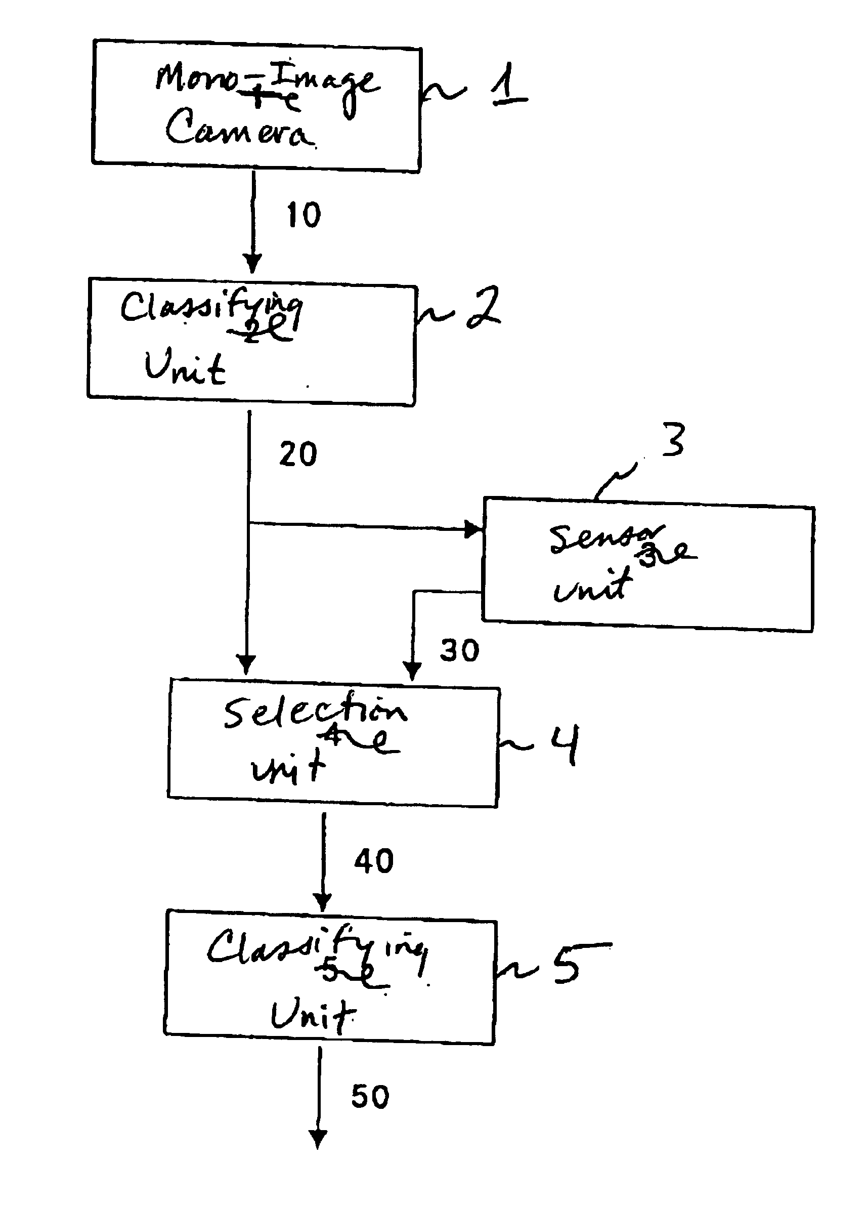
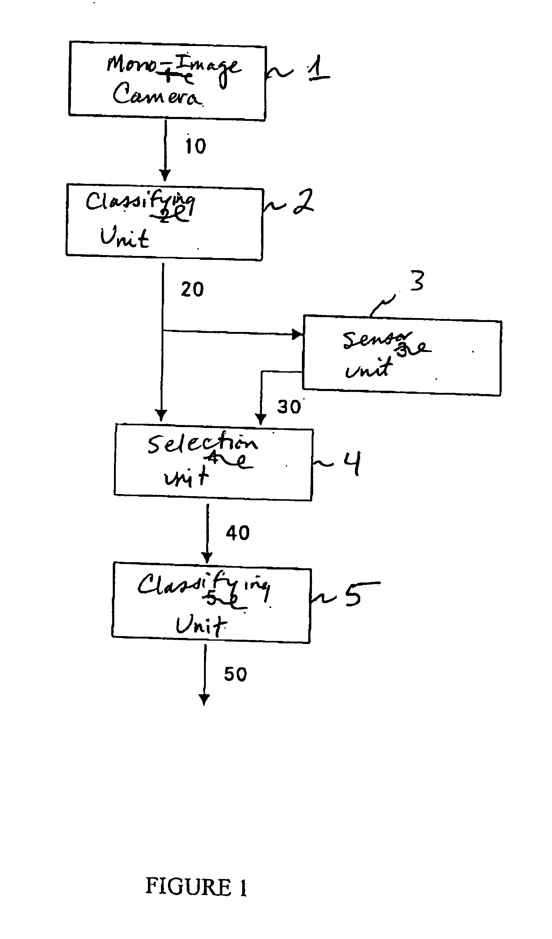
FIG. 1 schematically depicts one advantageous refinement of such a device for implementing the method of the present invention. Here, mono-image camera 1 makes image data 10 available to a classifying unit 2, which identifies image regions containing the road users or obstacles and informs distance-measuring sensor unit 3 of the corresponding positional data. Sensor unit 3 then measures these regions with respect to their distance from the observer. In so doing, these measuring data 30, together with data 20 from first classifying unit 2, are available to a selection unit 4. Selection unit 4 can control the data flow to the downstream unit for classifying selected road users or obstacles 5 by type. Image data 40 selected by the selection unit are transmitted to classifying unit 5 for classification. Results 50 of this type classification are advantageously made available to a risk calculator connected to the classifying unit, so that the risk calculator can decide whether to initiat...


PUM


Abstract

A method and a device for detecting road users and obstacles on the basis of camera images, in order to determine their distance from the observer and to classify them. In a two-step classification, potential other parties involved in a collision are detected and identified. In so doing, in a first step, potential other parties involved in a collision are marked in the image data of a mono-image camera; their distance and relative velocity are subsequently determined so that endangering objects can be selectively subjected to a type classification in real time. By breaking down the detection activity into a plurality of steps, the real-time capability of the system is also rendered possible using conventional sensors already present in the vehicle.

Description

BACKGROUND OF THE INVENTIONThe present invention is directed to a method for detecting road users and obstacles on the basis of camera images, and to a device for detecting road users and obstacles on the basis of camera images.By detecting an imminent collision between a road user and the vehicle of an observer at an early stage, one can improve the safety of vehicle occupants as well as of the potential other party involved in the collision. The time savings that can be gained by visually detecting and evaluating the observable region in front of the observer's vehicle permits stepped reactions of the vehicle occupant safety systems (e.g., a gentle firing of the airbag), or makes reactions possible in the first place to protect the other party in a collision (such as raising the engine hood in the case of collision involving a pedestrian). Developments culminating in switchable crash structures have made it more important than ever to know the type of other party involved in the a...

Claims


Application Information

Patent Timeline
IPC IPC(8): B60R21/01G08G1/16G06K9/00B60R21/00G03B15/00B60R21/0134B60R21/16B60W30/00G06T1/00G06V10/764G06V20/56
CPCB60R21/013G08G1/16G06K9/00B60R21/0134G08G1/165G08G1/166G06V20/56G06V10/764G06F18/24317G06F18/00
Inventor GLOGER, JOACHIMOBERLAENDER, MATTHIASWOLTERMANN, BERND
Owner DAIMLER AG
Why Eureka
Try Eureka