Vertical profile display with arbitrary plane

a vertical profile and plane technology, applied in the direction of instruments, measurement devices, climate sustainability, etc., can solve the problems of increasing the chance of an error occurring, the burden of manual labor of the pilot, and the limited display data of traditional radar systems, so as to reduce the task of piloting

Inactive Publication Date: 2005-01-04
HONEYWELL INT INC
View PDF10 Cites 62 Cited by
  • Summary
  • Abstract
  • Description
  • Claims
  • Application Information

AI Technical Summary

Benefits of technology

As will be readily appreciated from the foregoing summary, the invention provides a system for reducing pilot tasks when viewing weather radar return data.

Problems solved by technology

Traditional radar systems display data is limited to a line of sight starting from the aircraft-mounted radar antenna.
With existing systems, the burden is placed on the pilot to manually adjust the weather radar to obtain returns from where the aircraft will eventually fly.
When more burdens or tasks are required by a pilot to complete, the chance of an error occurring increases.

Method used


Image

  • Vertical profile display with arbitrary plane
  • Vertical profile display with arbitrary plane
  • Vertical profile display with arbitrary plane

Examples


Embodiment Construction

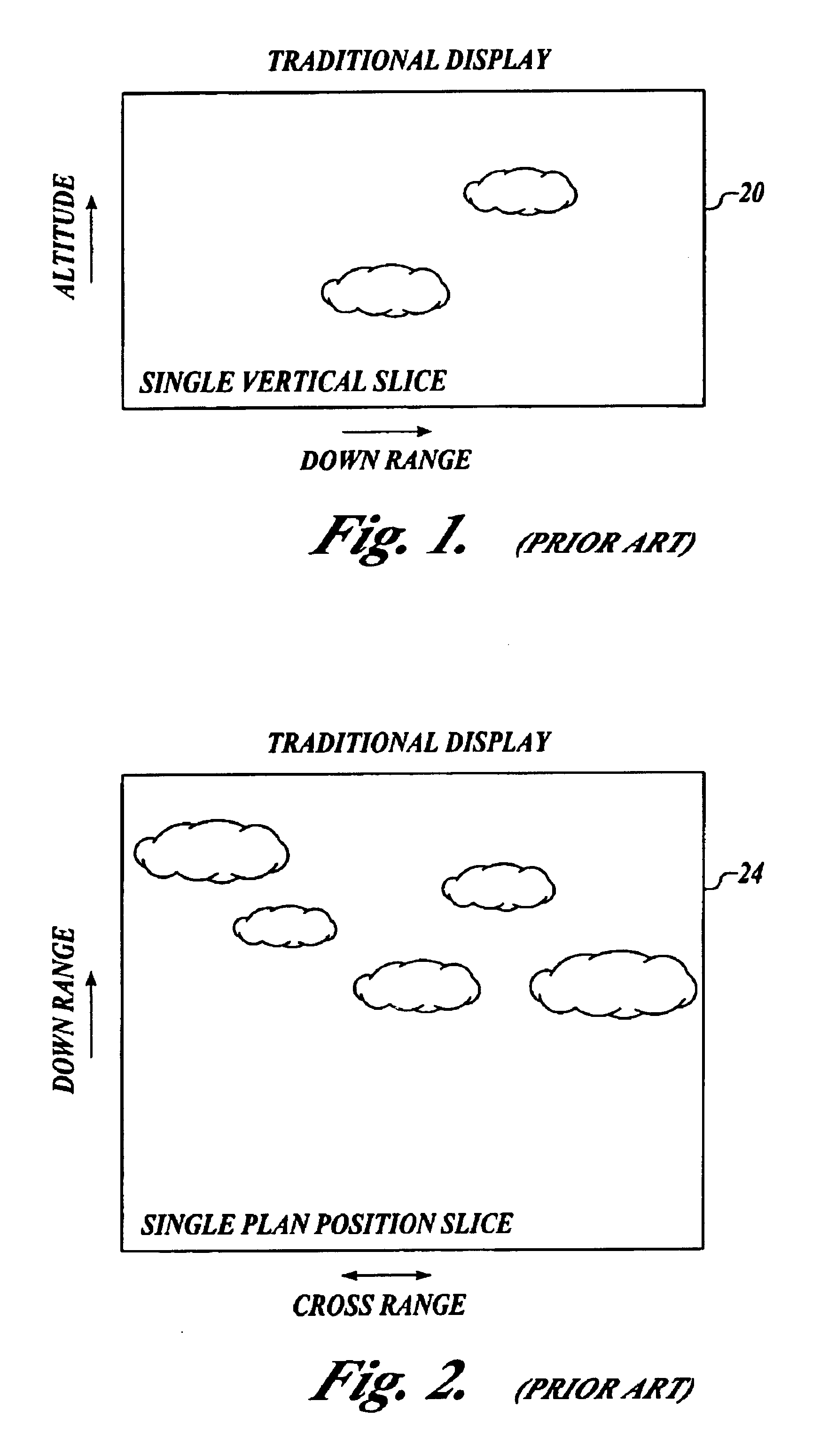
The present invention provides weather radar displays that allow pilots to quickly determine weather hazard-free flight paths and weather hazards that exist along the aircraft flight plan. FIGS. 1 and 2 illustrate prior art weather radar displays. FIG. 1 illustrates a single vertical slice image 20 of weather radar return information within a range of altitudes extending down range from an aircraft. The image 20 allows the pilot to determine if any weather radar return information (hazard information) exists in a vertical plane along the aircraft heading. The image 20 does not present any hazards that are in close proximity to the aircraft yet not along the vertical plane of the image 20. In order for the pilot to view hazards not in the vertical slice image 20, the pilot must select a plan position image 24 shown in FIG. 2. An additional viewing method is to sweep a vertical slice through azimuth. This is time consuming and requires more complicated processing. The plan position im...


PUM


Abstract

A system for allowing pilots to quickly determine weather hazard-free flight paths and weather hazards that exist along the aircraft flight plan. The system includes a memory, a processor, and a display device. The memory stores weather radar return information in a three-dimensional buffer. The processor is coupled to the memory. The processor receives a display distance value signal, retrieves weather radar return information stored in a plane of voxels in the three-dimensional buffer based on the selected display distance value and aircraft position information, and generates an image based on the retrieved weather radar return information. The display device is coupled to the processor for displaying the generated image.

Description

BACKGROUND OF THE INVENTIONTraditional radar systems display data is limited to a line of sight starting from the aircraft-mounted radar antenna. This is, in general, not where the aircraft is going to be flying, particularly throughout the course of a flight. Deviations in heading and altitude are common during a typical flight. With existing systems, the burden is placed on the pilot to manually adjust the weather radar to obtain returns from where the aircraft will eventually fly. When more burdens or tasks are required by a pilot to complete, the chance of an error occurring increases. Therefore, there exists a need to reduce pilot tasks—automate the weather radar display—in order to provide a safer flying environment.SUMMARY OF THE INVENTIONThe present invention comprises a system for allowing pilots to quickly determine weather hazard-free flight paths and weather hazards that exist along the aircraft flight plan. The system includes a memory, a processor, and a display device...

Claims


Application Information

Patent Timeline
Patent Type & Authority Patents(United States)
IPC IPC(8): G01S13/95G01S13/00G01S7/18G01S7/04G01S7/22G01S7/06G01S7/20
CPCG01S7/046G01S7/064G01S13/953G01S7/20G01S7/22G01S7/18Y02A90/10
Inventor SZETO, ROLAND Y.CORNELL, BILL G.
Owner HONEYWELL INT INC
Why Eureka
Try Eureka