Microstrip antenna employing width discontinuities

a microstrip antenna and discontinuous technology, applied in the field of microstrip antennas, can solve the problems of losing efficiency of conventional microstrip antennas at lower frequencies, and achieve the effects of reducing the size of microstrip antennas, and increasing the width

Inactive Publication Date: 2005-01-04
SOUTHERN METHODIST UNIVERSITY
View PDF8 Cites 122 Cited by
  • Summary
  • Abstract
  • Description
  • Claims
  • Application Information

AI Technical Summary

Benefits of technology

According to the present invention, an apparatus and method to reduce the size of a microstrip antenna without sacrificing antenna efficiency too much is described. When width discontinuities are introduced in a conventional rectangular microstrip antenna, the antenna size is substantially reduced and thus becomes electrically small with regard to a typical ½ wavelength radiating structure. Without more, a conventional microstrip antenna would lose efficiency at lower frequencies where the radiating surface is electrically small. The present invention addresses and resolves the antenna efficiency dilemma with conventional microstrip antennas by judicious placement of discontinuities in a width of the radiating structure.
The antenna structure includes discontinuity of strip width in a middle of an antenna patch to reduce the size of the antenna at a given resonant frequency, while not completely compromising radiation efficiency. The antenna structure includes a plurality of patches of differing widths connected to each other at one or more junctions. The junctions are symmetrically placed to ensure maximum radiation at the boresight and also to further reduce cross-polarization levels. A coaxial feed is connected at a predetermined location near the center of a patch of narrower width in order to match the input impedance of the antenna to the coaxial feed.
The antenna structure according to the present invention provides several advantages, over conventional antennas, such as low profile, easy fabrication and low cost. A simple structure is presented for size reduction of a microstrip antenna. Further, junctions formed by width discontinuities in the microstrip patch are effective in reducing the antenna size at a given resonant frequency without compromising radiation efficiency too much.
In another aspect, the present invention provides in an electrically short microstrip antenna having a ground plane, a dielectric layer, an electrically conductive layer overlying a surface of the dielectric layer, a method of reducing size of the microstrip antenna comprising providing a plurality of patches of differing widths on the conductive layer; connecting the plurality of patches to adjacent patches at one or more junctions, the connecting step including disposing a first patch among the plurality of patches between a second patch and a third patch of the plurality of patches, wherein the first patch has a narrower width compared to widths of the second and third patches, so that respective junctions formed between the first and second patch, and the first and third patch define discontinuities in width therebetween; and symmetrically placing the one or more junctions about the first patch so as to ensure maximum radiation at antenna boresight and to reduce cross-polarization levels.
In a further aspect, the present invention provides a microstrip antenna having a ground plane; a dielectric layer having a first surface overlying the ground plane, and a second surface opposing the first surface; a plurality of patches of differing widths disposed on a conductive layer on the dielectric layer; means for connecting the plurality of patches to adjacent patches at one or more junctions, a first patch among the plurality of patches being disposed between a second patch and a third patch, wherein the first patch has a narrower width compared to widths of the second and third patches, respectively; means for launching radio frequency energy; and means for ensuring maximum radiation at antenna boresight and suppressing cross-polarization levels.
In yet another aspect, the present invention provides a method for reducing a size of a microstrip antenna including disposing a first patch of predetermined width at a first location; joining the first patch to a second patch at at least two junctions, the second patch having narrower second width than the predetermined width of the first patch; connecting a third patch to the second patch at at least two junctions, the third patch having a greater width than the narrower second width; providing a feed in the second patch at a predetermined location so as to match input impedance of the antenna to the feed; and symmetrically placing the at least two junctions about the second patch so as to ensure maximum radiation at antenna boresight and to suppress cross-polarization levels.

Problems solved by technology

Without more, a conventional microstrip antenna would lose efficiency at lower frequencies where the radiating surface is electrically small.

Method used


Image

  • Microstrip antenna employing width discontinuities
  • Microstrip antenna employing width discontinuities
  • Microstrip antenna employing width discontinuities

Examples


Embodiment Construction

Obviously, readily discernible modifications and variations of the present invention are possible in light of the above teachings. It is therefore to be understood that within the scope of the appended claims, the invention may be practiced otherwise than as specifically described herein.

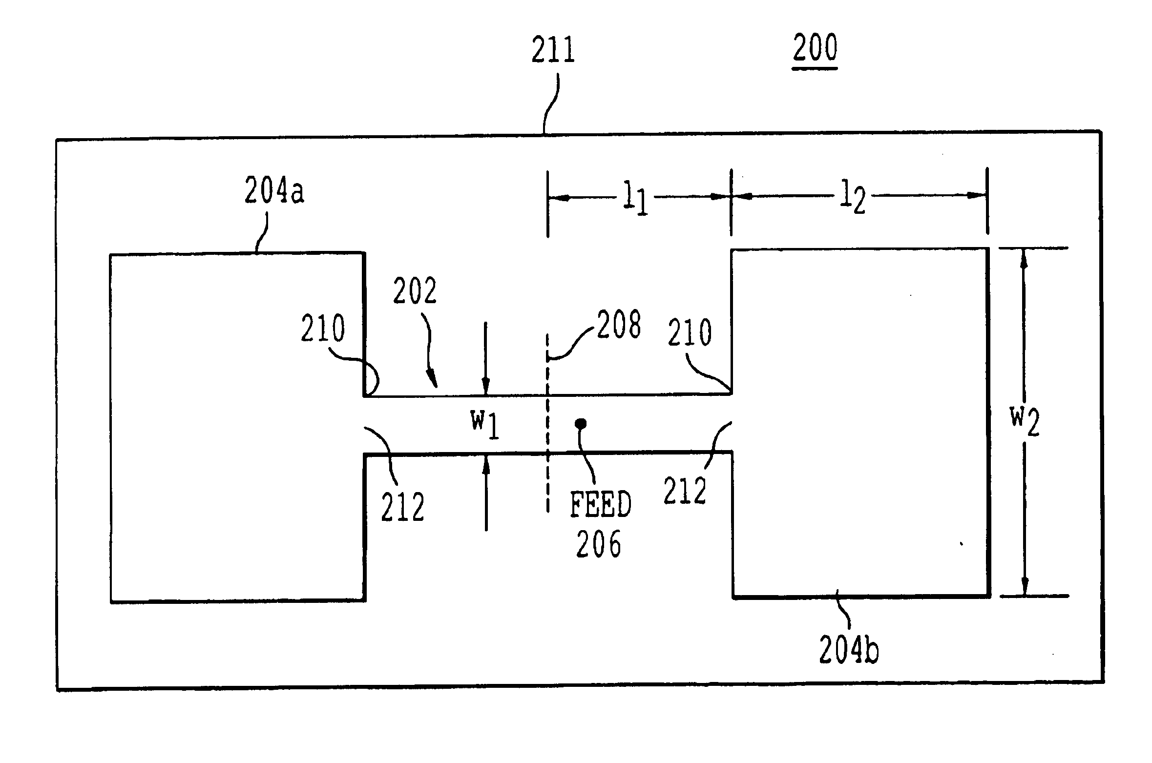
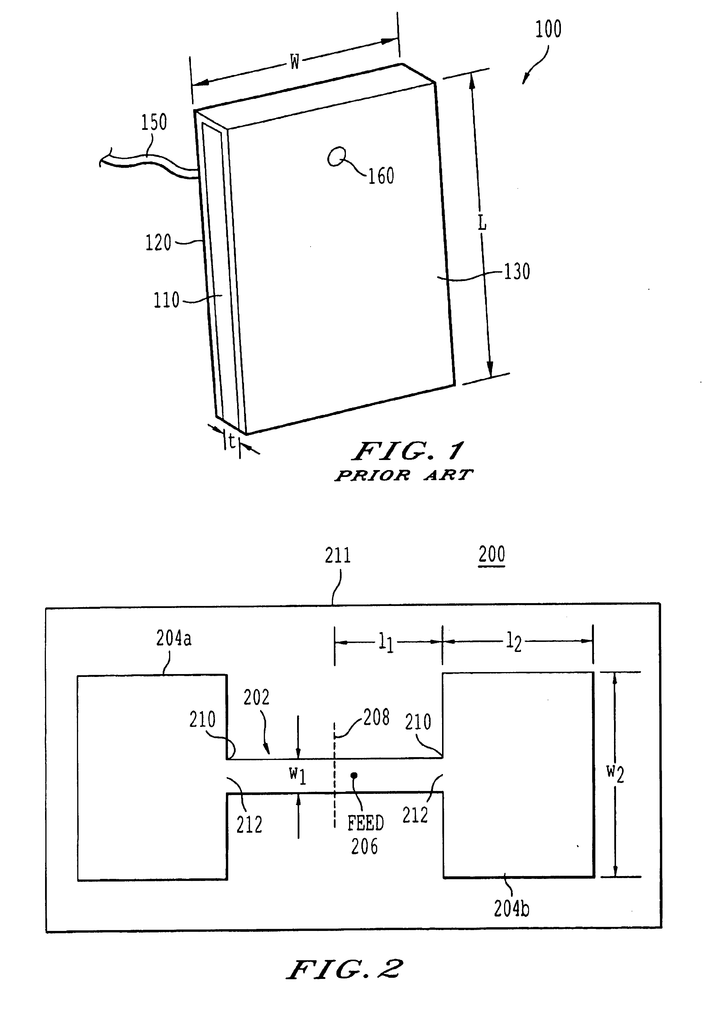
Referring to FIG. 2, there is shown a microstrip antenna 200 having a first patch 202 having a pair of edges 210. The first patch 202 includes a width w1 and a resonant length l1, wherein l1 is designated to indicate half of the resonant length of the first patch 202. The first patch 202 is flanked on either side of the edges 210 by a pair of patches 204a, 204b of resonant length l2 and width w2, the width w2 being larger when compared to the width w1 of the first patch 202. While the patches 204a, 204b are preferably identical, a tolerance of + / 10% size difference is believed to be acceptable. The first patch 202 is connected to patches 204a, 204b at junctions 212. The junctions 212 are placed symm...


PUM


Abstract

An apparatus and method to reduce the size of a microstrip antenna without sacrificing antenna efficiency too much are described. The antenna structure includes discontinuity of strip width in the middle of the antenna patch to reduce the size of the antenna at a given resonant frequency. The antenna structure further includes a plurality of patches of differing widths connected to each other at junctions. The junctions are placed symmetrically to ensure maximum radiation at the boresight and also to further reduce cross-polarization levels. A coaxial feed is connected at a predetermined location near the center of a patch, having a narrower width, in order to match the input impedance of the antenna to the coaxial feed.

Description

BACKGROUND OF THE INVENTION1. Field of the InventionThe present invention generally relates to microstrip antennas, and more particularly, to a microstrip antenna having symmetric width discontinuities at a patch portion for enabling reduction in antenna size without sacrificing antenna efficiency too much.2. Description of the Related ArtAdvances in digital and radio electronics have resulted in the production of a new breed of personal communications equipment posing special problems for antenna designers. As users demand smaller and more portable communications equipment, antenna designers are pressed to provide smaller profile antennas. Additionally, users of such communications equipment desire high data throughput, thus requiring antennas with wide bandwidths and isotropic radiation patterns. Moreover, antennas in such portable equipment are often randomly oriented during use, or used in environments, such as urban areas and inside buildings, that are subject to multipath refl...

Claims


Application Information

Patent Timeline
Patent Type & Authority Patents(United States)
IPC IPC(8): H01Q9/04H01Q21/00H01Q21/06
CPCH01Q9/0407H01Q21/065H01Q21/0006
Inventor LEE, CHOON SAE
Owner SOUTHERN METHODIST UNIVERSITY
Why Eureka
Try Eureka