

Liquid crystal display device
a liquid crystal display and display device technology, applied in the field of liquid crystal display devices, can solve the problems of luminance drop in fluorescent lamps, and achieve the effect of preventing luminance drop
- Summary
- Abstract
- Description
- Claims
- Application Information
AI Technical Summary
Benefits of technology
Problems solved by technology
Method used
Image

Examples
embodiment 1
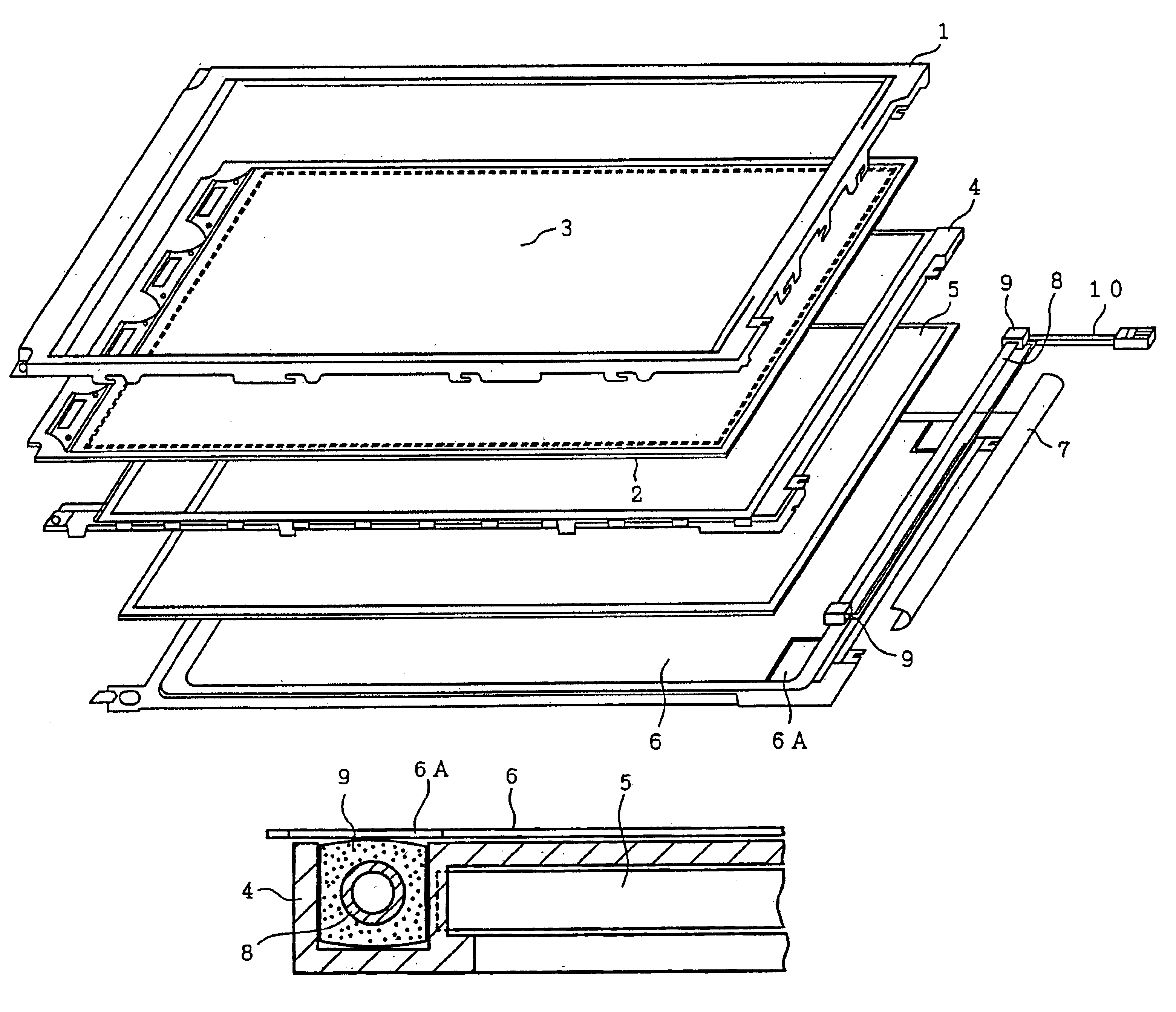
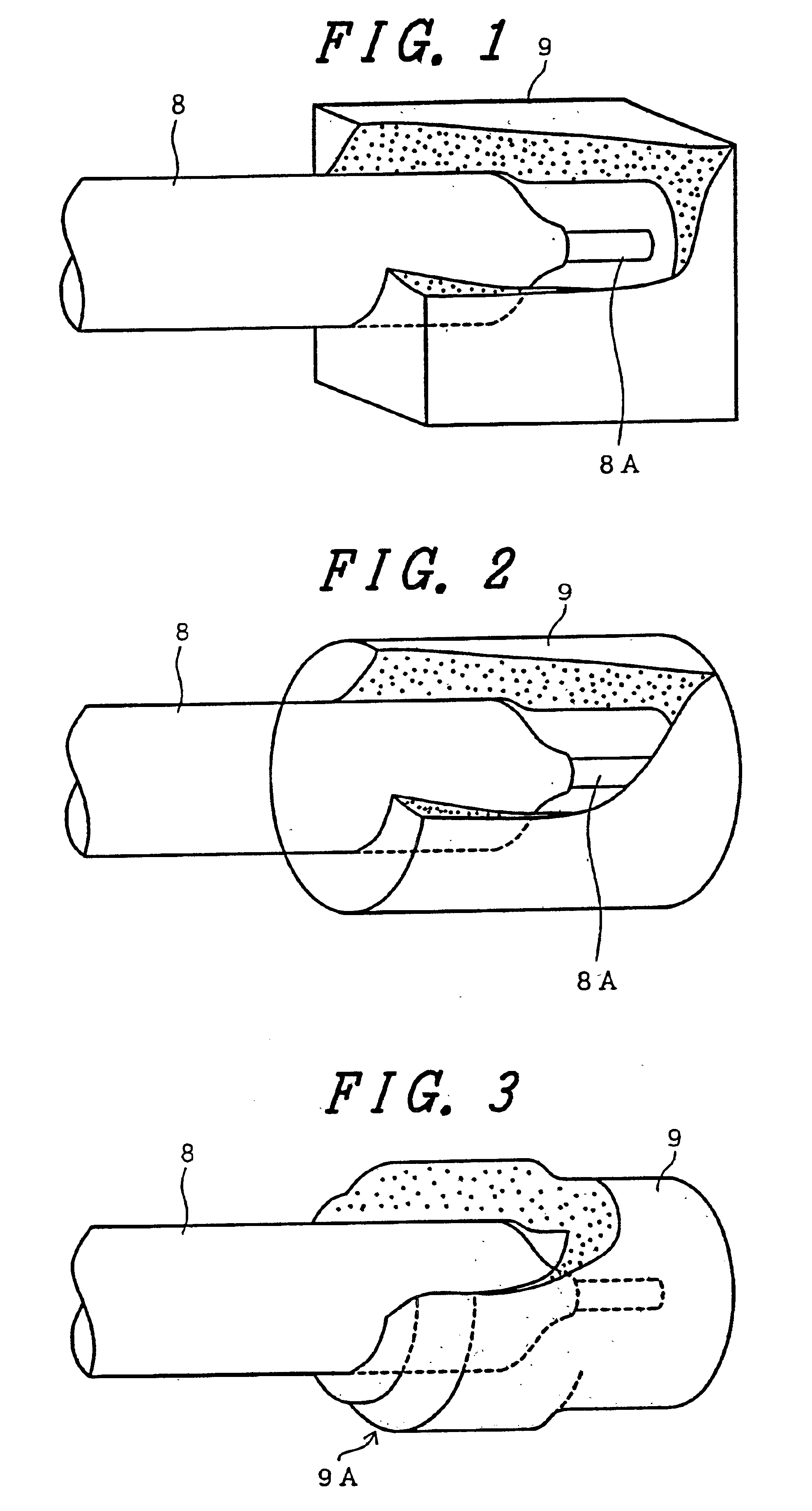
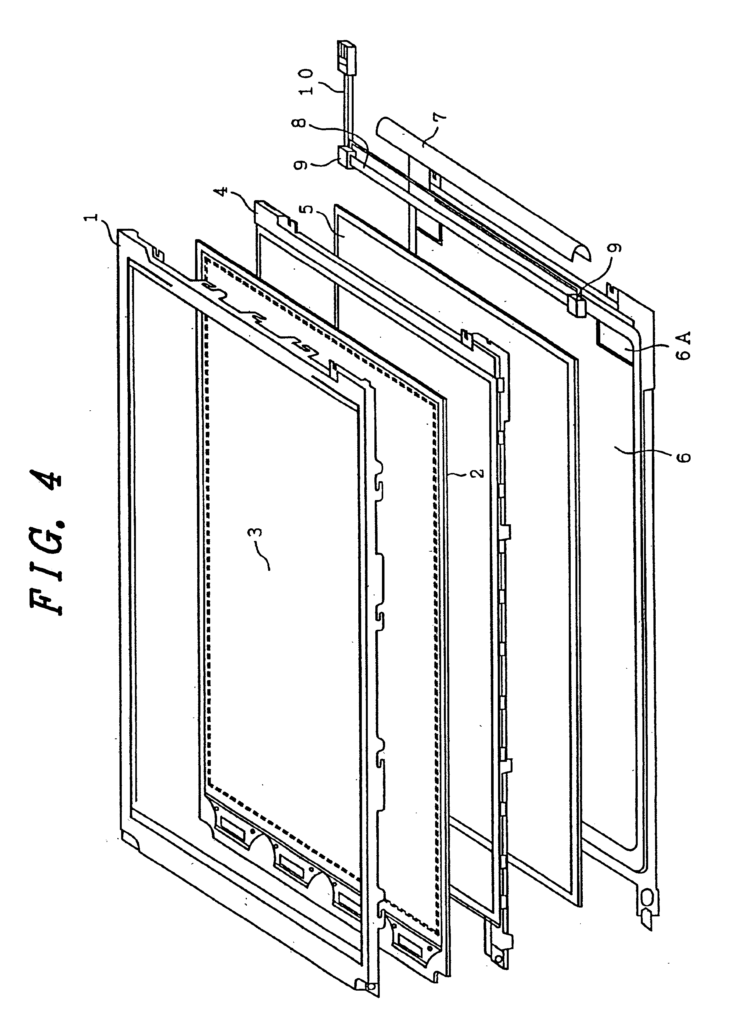
FIG. 1 is an enlarged view of a main portion in a luminaire (or, a lighting unit) for explaining a liquid crystal display device according to a first embodiment of the present invention, and shows a structure of an electrode portion of a fluorescent lamp as a linear light source (or, a tubular light source) constituting the luminaire.
In this embodiment, a cold cathode fluorescent lamp is utilized for the fluorescent lamp 8, and the electrode portions at both ends thereof are inserted elastically into lamp holders 9 respectively. These lamp holders 9 are flexible, has an almost rectangular exterior, and has an opening for inserting an end of the fluorescent lamp 8 into a cavity formed therein on one of surfaces thereof. This cavity has a dead end in the lamp holder 9, but may have a tunnel-like shape which pierces through the lamp holder 9 to another surface thereof opposite to the surface having the opening.
An electrode terminal 8A is pulled out from the electrode portion of the flu...
embodiment 2
FIG. 2 is an enlarged view of a main portion in a luminaire for explaining a liquid crystal display device according to a second embodiment of the present invention, and shows a structure of an electrode portion of a fluorescent lamp as a linear light source constituting the luminaire.
A difference in this embodiment from the aforementioned first embodiment is that the lamp holder has an almost cylindrical exterior, and has an opening for inserting an end of the fluorescent lamp 8 into a cavity formed therein on one of end surfaces thereof. This cavity has a dead end in the lamp holder 9, but may have a tunnel-like shape which pierces through the lamp holder 9 to another side thereof opposite to the surface having the opening.
According to this embodiment also, heat in the electrode portion of the fluorescent lamp 8 is retained by setting the fluorescent lamp equipped with the lamp holder 9 in an intermediate old frame as shown in FIG. 11 so that a temperature drop of the electrode po...
embodiment 3
In FIG. 3 is an enlarged views of a main portion in a luminaire for explaining a liquid crystal display device according to a third embodiment of the present invention, and shows a structure of an electrode portion of a fluorescent lamp as a linear light source constituting the luminaire.
In this embodiment, the lamp holder 9 is shaped into an almost cylindrical exterior like that of the second embodiment, and has an opening for inserting an end (an electrode portion) of the fluorescent lamp 8 into a cavity formed therein on one of end surfaces thereof also. An external diameter of a circumference 9A around this opening is varied along a longitudinal direction of the fluorescent lamp 8 so as to adhere to outer wall of the fluorescent lamp. This cavity in this embodiment has a dead end in the lamp holder 9 also, but may have a tunnel-like shape which pierces through the lamp holder 9 to another side thereof opposite to the surface having the opening.
According to this embodiment also, ...
PUM
 Abstract
Description
Claims
Application Information