Optical amplifying apparatus and optical communication system
a technology of optical communication system and amplifier, which is applied in the field of optical amplifier and optical communication system, can solve problems such as limiting transmission distance, and achieve the effect of lengthening transmission distan
- Summary
- Abstract
- Description
- Claims
- Application Information
AI Technical Summary
Benefits of technology
Problems solved by technology
Method used
Image

Examples
first embodiment
Structure of a First Embodiment
The first embodiment relates to an optical amplifying apparatus according to the present invention.
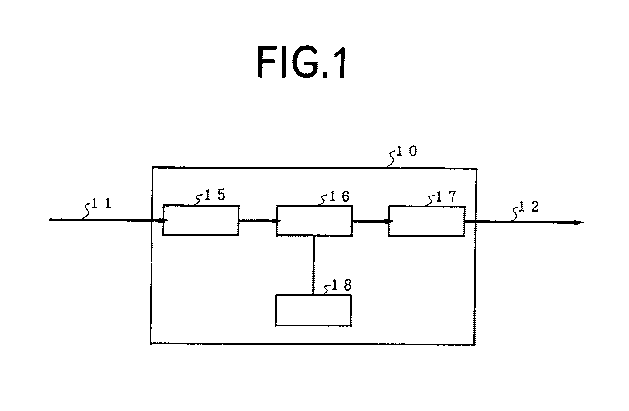
FIG. 1 is a view showing the structure of the optical amplifying apparatus according to the first embodiment.
As in FIG. 1, according to the first embodiment, it is structured by an optical amplifying apparatus 10 in which light outputted to an optical transmission line 12 is amplified with a gain as a function of wavelength which almost compensates for a loss as a function of wavelength of the optical transmission line 12.
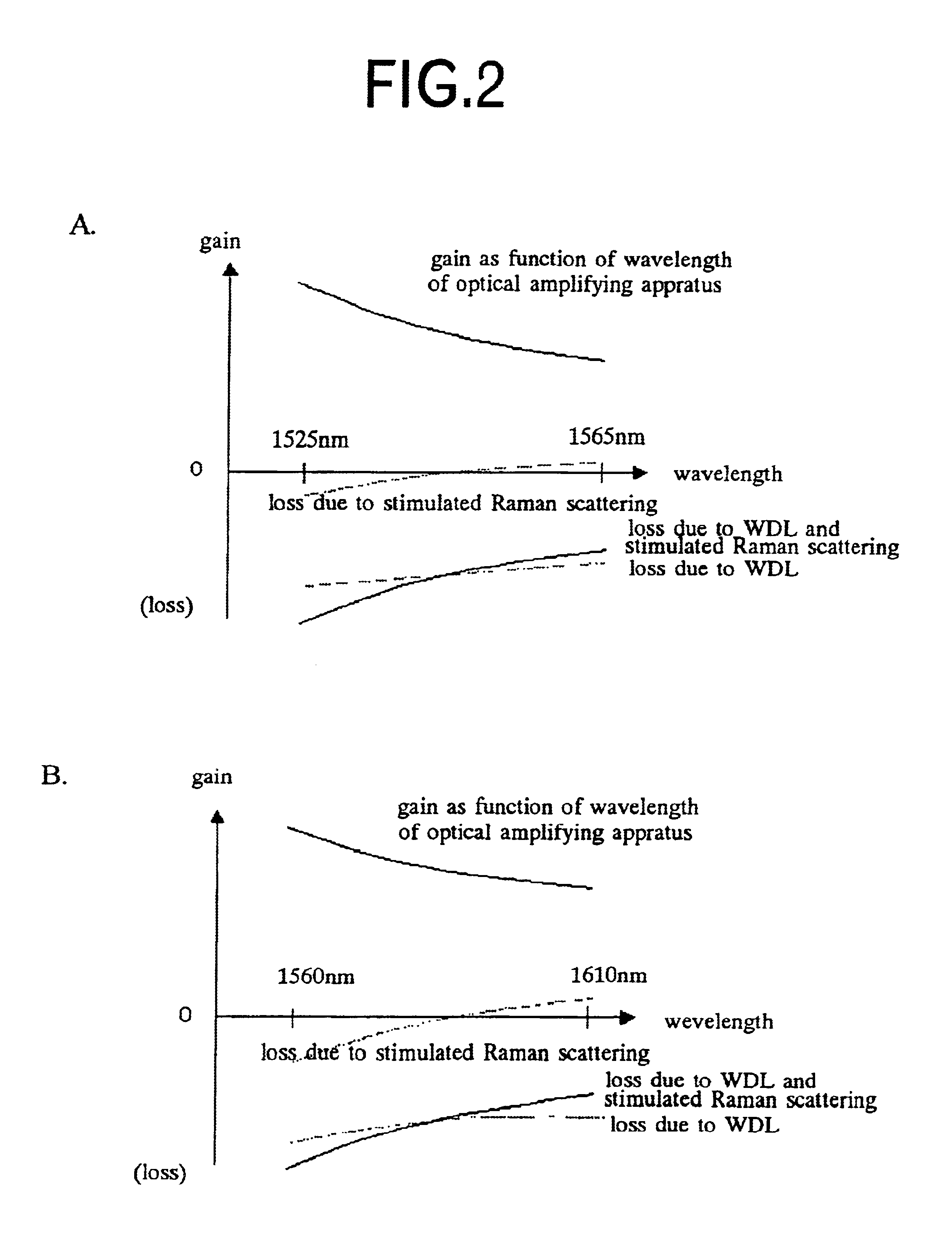
The first embodiment relates to an invention in which, when the optical amplifying apparatus 10 outputs light in a certain wavelength band, a difference between a loss in a short wavelength side of the light and a loss in a long wavelength side thereof is compensated in advance.
The difference is caused due to a loss as a function of wavelength of the optical transmission line 12 while output light transmits through the optical transmissi...
second embodiment
FIG. 4 is a view showing the structure of an optical amplifying apparatus according to the second embodiment.
As in FIG. 4, in a complex optical amplifying apparatus 20 according to the second embodiment, for wavelength-multiplexing outputs from a plurality of optical amplifying parts 21 which have different wavelength bands to amplify light from each other and outputting it to an optical transmission line 26, each of the plurality of the optical amplifying parts 21 is structured to amplify the light to be amplified with a gain as a function of wavelength which almost compensates for a loss as a function of wavelength of the optical transmission line 26.
Since (formula 1) to (formula 10) holds also for a WDM optical signal in which optical signals are set in a plurality of the wavelength bands corresponding to the plurality of the optical amplifying parts 21, a compensation amount SL can be determined similarly to the above. Hence, the optical amplifying parts 21 are adjusted by the c...
fourth embodiment
Structure of a Fourth Embodiment
The fourth embodiment is an embodiment of an optical communication system according to the present invention. In the optical communication system of the fourth embodiment, a 32-wave WDM optical signal is transmitted between two terminal stations while being amplified in sequence by a plurality of optical amplifying apparatuses according to the present invention.
PUM
| Property | Measurement | Unit |
|---|---|---|
| wavelength bandwidth | aaaaa | aaaaa |
| transmission distance | aaaaa | aaaaa |
| loss wavelength | aaaaa | aaaaa |
Abstract
Description
Claims
Application Information
 - R&D
- Intellectual Property
- Life Sciences
- Materials
- Tech Scout
- Unparalleled Data Quality
- Higher Quality Content
- 60% Fewer Hallucinations
Browse by: Latest US Patents, China's latest patents, Technical Efficacy Thesaurus, Application Domain, Technology Topic, Popular Technical Reports.
© 2025 PatSnap. All rights reserved.Legal|Privacy policy|Modern Slavery Act Transparency Statement|Sitemap|About US| Contact US: help@patsnap.com