
Reflection type diffraction grating

a diffraction grating and reflection metal technology, applied in the field of spectroscopic optical devices, can solve the problems of inferior oxidation resistance of al film, insufficient mechanical strength of au film, and insufficient weather resistance and abrasion resistance of these reflection metal films

Inactive Publication Date: 2005-01-04
NIPPON SHEET GLASS CO LTD
View PDF11 Cites 34 Cited by
  • Summary
  • Abstract
  • Description
  • Claims
  • Application Information

AI Technical Summary

Benefits of technology

The present invention is devised to solve the aforementioned problems and an object of the invention is to provide a reflection type diffraction grating in which the intensity of reflected light can be obtained without lowering of reflectance and regardless of the state of polarization of incident light.

Problems solved by technology

If such reflection metal films are used in a state of being exposed to an environment, weather resistance and abrasion resistance of these reflection metal films may be insufficient.
Particularly it is known that an Al film is inferior in oxidation resistance.
An Au film is insufficient in mechanical strength.
There arises a problem that information processing of such light is made complex.
In the proposed method, however, insertion loss is produced because of the inserted device as well as the optical system is made complex because of increase in the number of devices.
There is a problem that the intensity of light is lowered.

Method used


Image

  • Reflection type diffraction grating
  • Reflection type diffraction grating

Examples


example 1

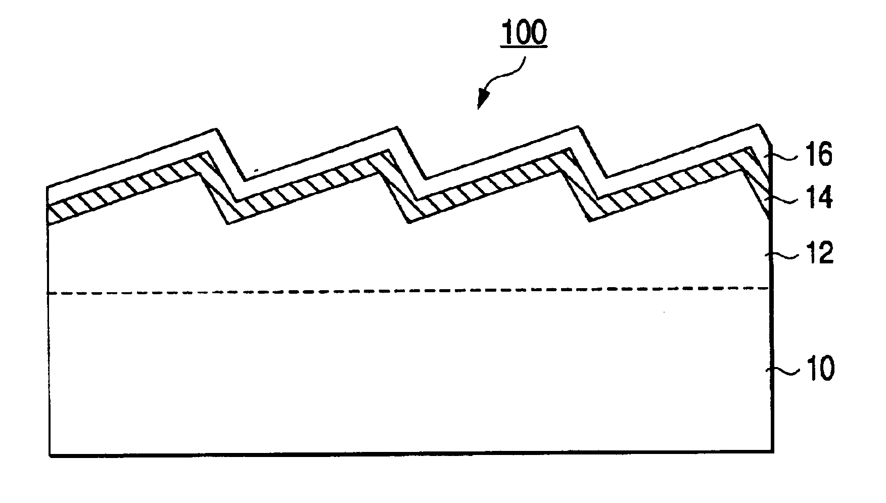
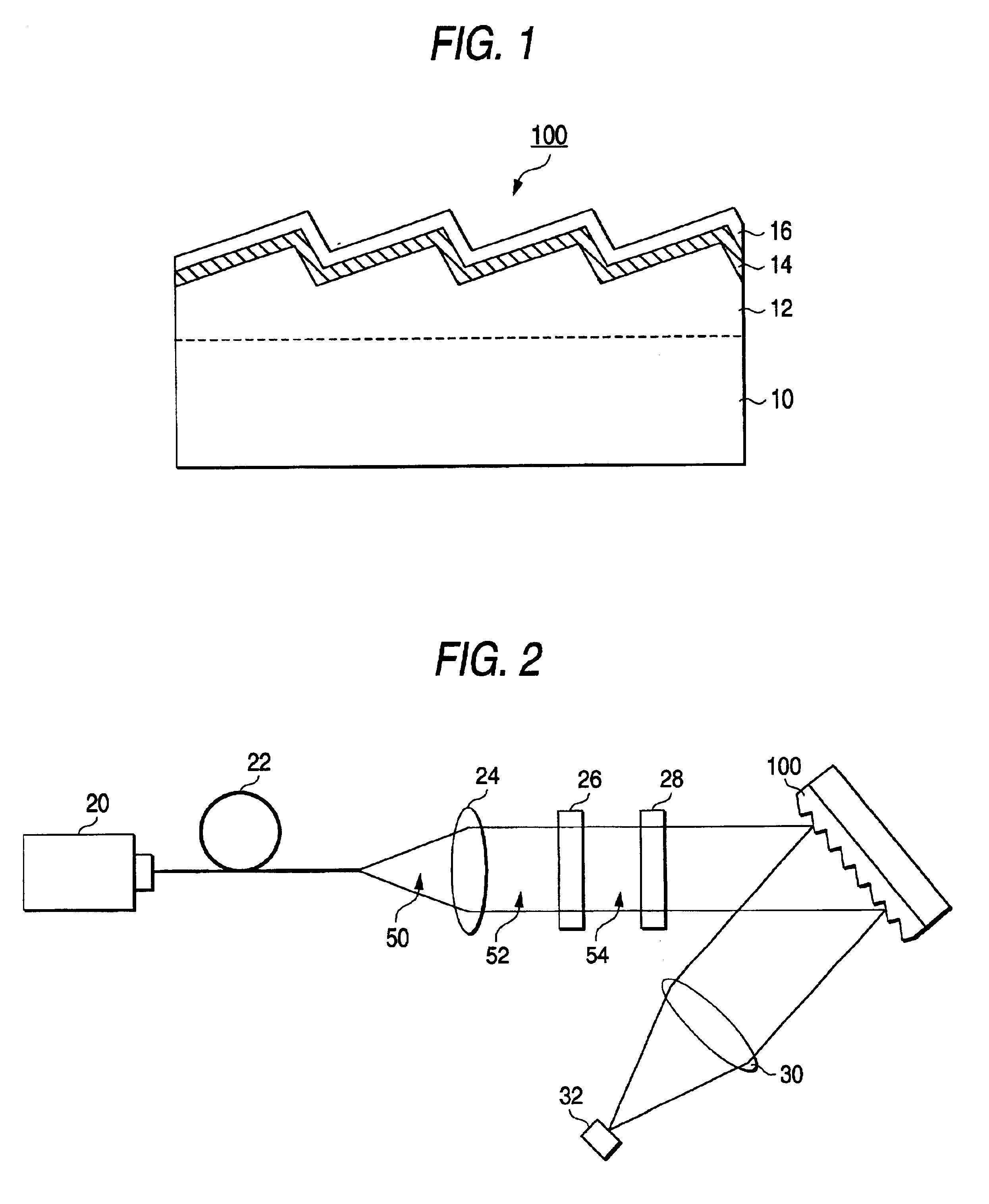
A fine roughness structure of a diffraction grating according to the present invention was produced by the following method. First, a sol solution containing a liquid hydrolysate of methyltriethoxysilane as a main component was applied onto a glass substrate 10 shown in FIG. 1 by spin coating, This sol-solution-applied substrate 10 was press-molded while a brazed replica diffraction grating (900 / mm) which was subjected to mold release treatment and which was available on the market was used as a stamping mold. Then, mold release treatment and baking were performed to thereby obtain a fine roughness structure 12 serving as a diffraction grating. The depth of each of the roughness grooves was about 1 μm. Al was vacuum-deposited on a surface of the fine roughness structure to thereby form a metal film 14 with a thickness of 100 nm. The reflectance of the Al film was not lower than 90% with respect to non-polarized light. Silicon dioxide (SiO2) and titanium dioxide (TiO2) were vacuum-de...

example 2

Al and magnesium fluoride (MgF2) were deposited on a holographic replica diffraction grating (900 / mm, provided with a reflection Al film formed thereon) available on the market to thereby form two layers 100 nm and 250 nm thick respectively. That is, this Example has two metal films (an Al film originally provided on the holographic replica diffraction grating, and another Al deposited on the holographic replica diffraction grating). The diffraction efficiency of the thus produced diffraction grating with respect to the wavelength of 1550 nm was measured in the same manner as that in Example 1. As a result, the diffraction efficiency of the diffraction grating having an Al single layer was 32.8% with respect to the TE-polarized light and 82.5% with respect to the TM-polarized light whereas the diffraction efficiency of the diffraction grating having the dielectric film formed on the Al layer was 41.9% with respect to the TE-polarized light and 54.9% with respect to the TM-polarized ...


PUM


Abstract

A reflection type diffraction grating according to the present invention has a structure in which a metal film as a first layer with reflectance not lower than 30% with respect to the wavelength of incident light and a transparent dielectric film as a second layer are laminated successively on the surface of the reflection type diffraction grating. With respect to the wavelength of incident light, the metal film has a refractive index selected to be not higher than 1.5 and an extinction coefficient selected to be not smaller than 6.0. The transparent dielectric film has a refractive index selected to be in a range of from 1.30 to 1.46, both inclusively, with respect to the wavelength of incident light and has an optical film thickness selected to be in a range of from 0.20λ to 0.38λ, both inclusively, when λ is the wavelength of incident light.

Description

BACKGROUND OF THE INVENTIONThe present invention relates to a spectroscopic optical device, especially to a reflection type diffraction optical device used widely in an optical technology field such as an optical sensor, an information recording device, an optical measuring device, and so on.Diffraction gratings are used popularly as spectroscopic optical devices or optical demultiplexing devices. Among these diffraction gratings, a reflection type diffraction grating using diffracted light as reflected light is, in most cases, configured in such a manner that a metal film is formed as a reflection film on a surface of a member having grooves formed periodically so as to improve reflection efficiency of the reflection type diffraction grating. A high-reflectance material such as Al, Au, or the like, is used as the metal film provided on the surface of the periodically grooved member.If such reflection metal films are used in a state of being exposed to an environment, weather resist...

Claims


Application Information

Patent Timeline
Patent Type & Authority Patents(United States)
IPC IPC(8): G02B5/18
CPCG02B5/1861G02B5/18
Inventor SHIMMO, KATSUHIDEKAWAMOTO, SHINJIKUNISADA, TERUFUSANAKAMA, KENICHI
Owner NIPPON SHEET GLASS CO LTD
Learn More