
Reflector for light-emitting diode and housing

Inactive Publication Date: 2014-03-06
DUPONT MITSUI FLUOROCHEMICALS CO LTD
View PDF3 Cites 11 Cited by
  • Summary
  • Abstract
  • Description
  • Claims
  • Application Information

AI Technical Summary

Benefits of technology

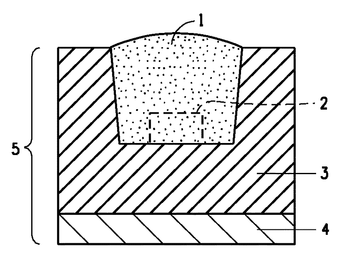
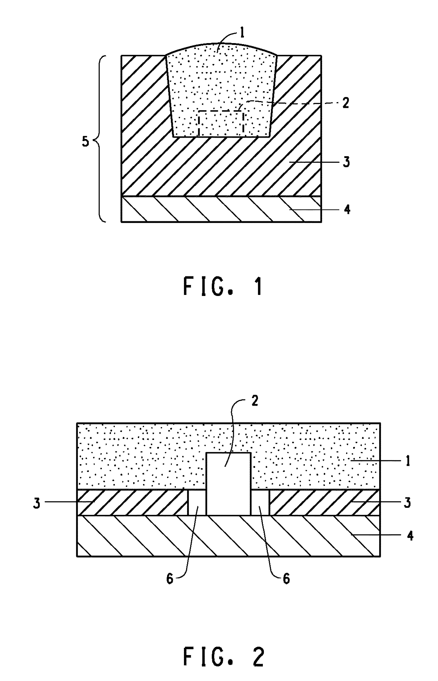
The present invention relates to a reflector that has good heat resistance, light resistance, and weather resistance. The reflector is designed to maintain its reflectance from ultraviolet to visible light. Additionally, a housing containing the reflector is also provided. This invention allows for the creation of an efficient, durable reflector for LED applications.

Problems solved by technology

In molding of the ceramic, since the ceramic was heated to a temperature of 1,000° C. or higher and baked for a certain time in a batch process, the manufacture cost was high, and the productivity was poor.
In addition, since the polyamide group resin was apt to be degraded at high temperature, when the resin was melted and molded, if the residence time in a melting molding machine was lengthened, the resin was thermally decomposed and discolored, so that the manufacture loss was increased, thereby deteriorating the productivity.
In this system, since the wavelength of an excitation light source is further shortened from 460 nm of a blue color to 405 nm, the housing member is likely to be further degraded beyond the current level, thus being unable to expect a long life of the LED housing.
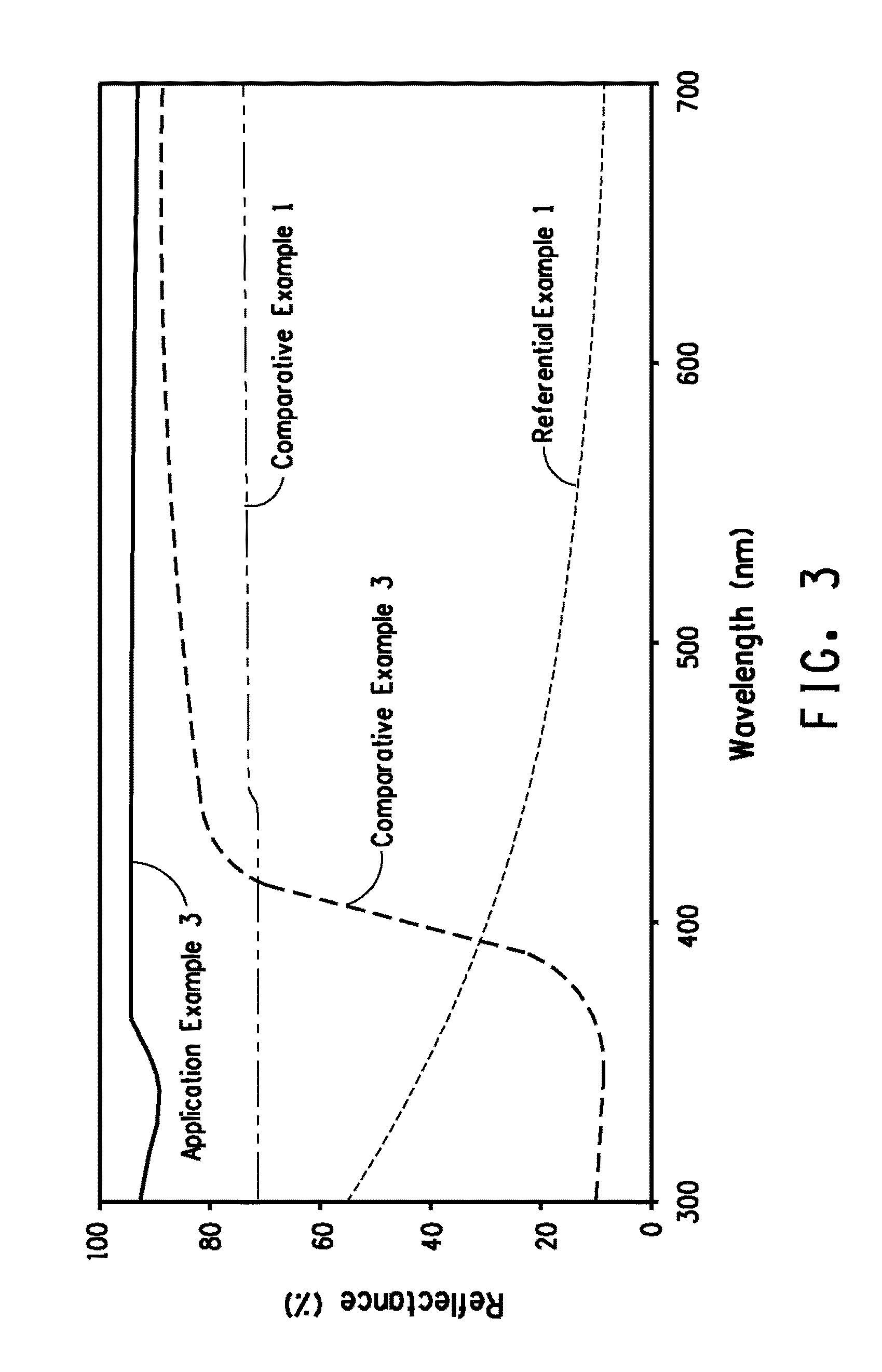
However, like the aforementioned polyamide group resin (Comparative Example 3 of the instant application), since the titanium dioxide for absorbing ultraviolet rays is used as a filler, the reflectance in an ultraviolet region is largely lowered (see Comparative Example 2 of the instant application), and this fluororesin cannot be used in a reflector for ultraviolet LED and a reflector for white LED in which a rear-ultraviolet LED is combined with fluorescent materials with three colors of red, green, and blue.

Method used


Image

  • Reflector for light-emitting diode and housing
  • Reflector for light-emitting diode and housing
  • Reflector for light-emitting diode and housing

Examples


examples

[0053]Next, the present invention will be explained in further detail by application examples and comparative examples; however, the present invention is not limited by this explanation.

[0054]Each property in the present invention was measured by the following methods.[0055]A. Measurement of Properties

[0056](1) Melting Point (Melting Peak Temperature)

[0057]A differential scanning calorimeter (Pyris 1 type DSC, made by Perkin Elmer Co.) was used. About 10 mg sample was weighed, put into a dedicated aluminum pan, crimped by a dedicated crimper, and housed in the DSC body, and the temperature was raised at 10° C. / min from 150° C. to 360° C. At that time, the melting peak temperature (Tm) was attained from the melting curve obtained.

[0058](2) Melt Flow Rate (MFR)

[0059]Using a melt indexer (made by Toyo Seiki Co., Ltd.) with a corrosion-resistant cylinder, die, and piston based on ASTM D-1238-95, 5 g sample powder was filled in the cylinder held at 372±1° C., held for 5 min, and extruded...

application examples 1-3

[0077]Alumina (A16GS) and fluororesin PFA with compositions shown in Table 1 were melt-kneaded at 350° C. and 100 rpm for 5 min by using the melt-kneader (made by Toyo Seiki Works K.K., KF-70 V small-scale segment mixer) in combination of shears in which the phase of five sheets of kneading discs was shifted by 2 pitch, so that mixed compositions were obtained. From the fracture surfaces of the composite compositions (FIGS. 4A and 4B) obtained, the alumina dispersed state was evaluated by an electron microscope. As a result, it was understood that the alumina was uniformly dispersed into FFA. In addition, the composite compositions underwent melt-compression molding at 350° C. to prepare samples with a thickness of about 1.5 mm. The reflectance of the samples was measured at standard temperature. The results obtained were summarized in Table 1.

application example 4

[0078]The composite composition prepared by Application Example 3 underwent melt-compression molding at 350° C. to prepare a sample with a thickness of about 1.5 mm. The sample obtained was put into a hot-air circulation type oven, whose temperature was raised to 150° C., and then heat-treated for 100 h, and the reflectance of the sample was measured at standard temperature. The results obtained were summarized in Table 2.


PUM

PropertyMeasurementUnit
Percent by massaaaaaaaaaa
Wavelengthaaaaaaaaaa
Particle diameteraaaaaaaaaa

Abstract

Provided is a reflector for a light-emitting diode which has a small decrease in reflectance in a range from the ultraviolet region to visible region, and has excellent heat resistance, light resistance, and weather resistance, and a housing having this reflector. The reflector for a light-emitting diode is obtained by molding a fluororesin composition containing a filler with an average particle diameter of smaller than 1 μm, wherein the difference between the maximum value and the minimum value of the reflectance at a wavelength of 240-700 nm is within 25%.

Description

FIELD OF INVENTION[0001]The present invention relates to a reflector for a light-emitting diode (alternately referred to herein as LED) having high reflectance, and having a small decrease in reflectance in a range from ultraviolet to visible. The reflector has excellent heat resistance, light resistance, and weather resistance. The present invention further relates to a housing for light-emitting diodes having said reflector.BACKGROUND OF INVENTION[0002]Recently, light-emitting diode elements (alternately referred to herein as LED chips) are small in scale and can be it over a long period of time, compared with filament electric bulbs. Since their conversion efficiency of electric energy into a light is high, there is a strong tendency that these elements replace conventional illuminators including a straight tube type fluorescent lamp, and these diode elements are broadly used as electric home appliances, LED displayers, and lighting type operation switches. The usages of LED are ...

Claims


Application Information

Patent Timeline
IPC IPC(8): F21V7/22
CPCF21V7/22B29C43/003H01L33/60B29K2027/12B29K2105/06B29K2995/003H01L2924/0002F21V7/28F21V7/26H01L2924/00
Inventor NAM, PHAM HOAI
Owner DUPONT MITSUI FLUOROCHEMICALS CO LTD
Learn More