
Multi-media E-mail system and device for transmitting a composed return E-mail

a multi-media, return e-mail technology, applied in the field of multi-media e-mail system and device, can solve the problems of volume to be transmitted, inability to synchronize audio associated with text, network deficiency, etc., and achieve the effect of reducing the volume of information going through the network

Inactive Publication Date: 2005-01-04
PANASONIC INTELLECTUAL PROPERTY CORP OF AMERICA
View PDF16 Cites 34 Cited by
  • Summary
  • Abstract
  • Description
  • Claims
  • Application Information

AI Technical Summary

Benefits of technology

Therefore, an object of the present invention is to provide a multi-media E-mail system and device that transmits / receives, through a network, multi-media E-mails each having various types of media information being temporally and / or spatially related to one another, and further, reduces information volume going through the network.
In this manner, when such multi-media E-mail that various types of media information included therein is each temporally and / or spatially related to one another is transmitted / received through a network, received media information does not go through the network twice. Therefore, information volume going therethrough can be reduced.
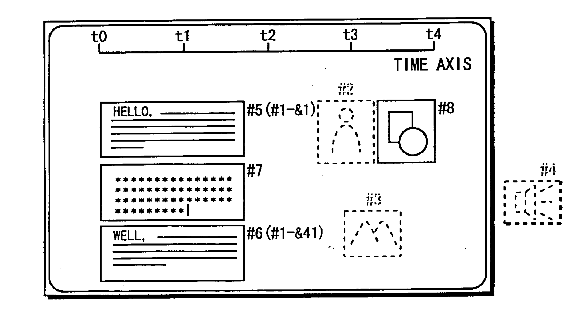
Further, when the received media information is divided, the multi-media E-mail to be transmitted to the sender further includes division controlling information indicating at where the received media information is divided (for example, when the received media information is moving images, it is represented by frame number, and text data by line number) as an alternative to the divided media information. Accordingly, as the divided media information is not sent back to the sender, information volume going through a network can be reduced.
As described above, in the third aspect, media information included in a mail (outgoing mail) to be transmitted is stored as transmitted media information. If a return mail for the outgoing mail is received, media information included in the received multi-media E-mail and previously-stored transmitted media information is positioned according to positioning control information included in the multi-media E-mail. In this manner, the incoming mail (return mail) can be restored.
Further, when the received media information is divided, a multi-media E-mail to be transmitted back to the sender further includes the divided media information indicating at where the received media information is divided (for example, when the received media information is moving images, it is represented by frame number, and text data by line number) as an alternative to the divided media information. Accordingly, as the divided media information is not sent back to the sender, information volume going through a network can be reduced.
Still further, when a return mail is received, divided media information is first generated from the transmitted media information according to the division controlling information, and then the media information included in the received multi-media E-mail and the generated divided media information is positioned according to the positioning control information included in the multi-media E-mail. In this manner, the incoming mail (return mail) can be restored.

Problems solved by technology

In such conventional E-mail systems that transmit images or audio information in the attachment file, however, audio associated with text does not synchronize with the text, or images are not switched in synchronization with audio.
It is predictable, however, the information volume to be transmitted will see a leap as the multi-media E-mail system becomes prevalent, and resultantly networks will be deficient in capacity.
At the same time, as the audio or image is much larger in volume than the text, time and cost required for the communications will be an issue for users.
Nevertheless, the other conventional system has not been working out and applying any solution to decrease the to-be-increased information volume.

Method used


Image

  • Multi-media E-mail system and device for transmitting a composed return E-mail
  • Multi-media E-mail system and device for transmitting a composed return E-mail
  • Multi-media E-mail system and device for transmitting a composed return E-mail

Examples


first embodiment

(First Embodiment)

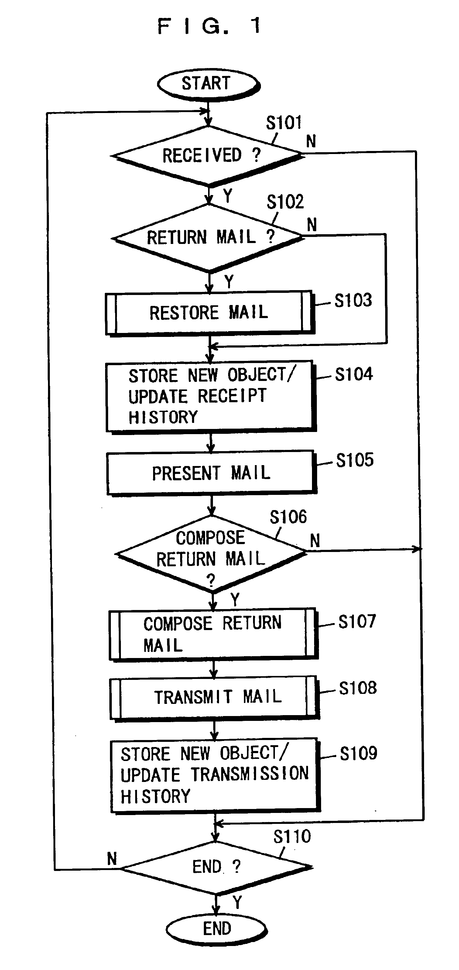
FIG. 1 is a flowchart illustrating a multi-media E-mail system according to a first embodiment of the present invention.

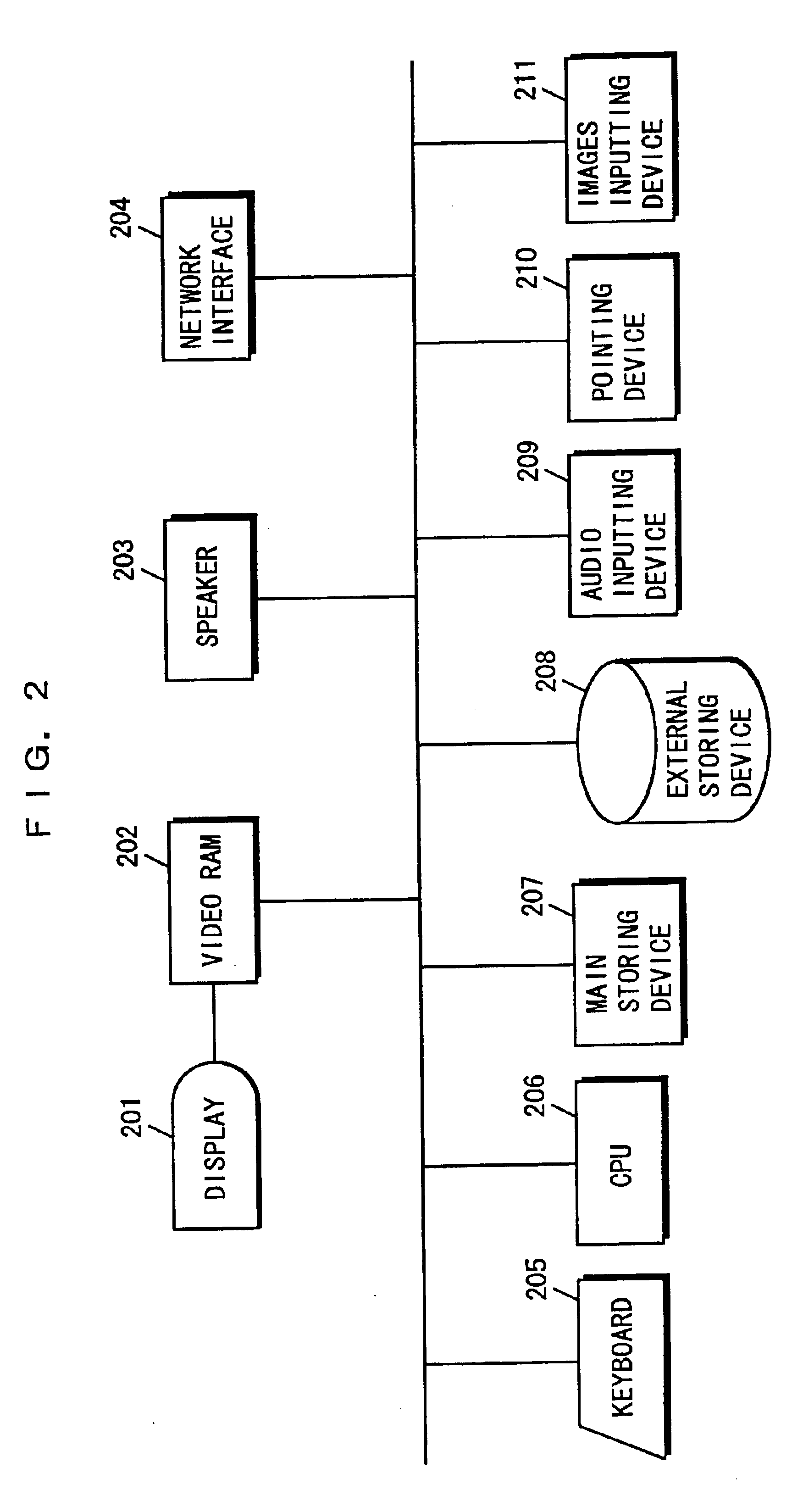
FIG. 2 is a block diagram showing the configuration of components in a computer system which realizes the multi-media E-mail system shown in FIG. 1.

In FIG. 2, the computer system is provided with a display 201, a video RAM 202, a speaker 203, a network interface 204, a keyboard 205, a CPU 206, a main storing device 207, an external storing device 208, an audio inputting device 209, a pointing device 210, and an images inputting device 211.

The display 201 displays text (text information) and images (image information). The speaker 203 outputs audio information. The network interface 204 is an interface device for connecting the computer system to a not-shown network. The keyboard 205 responds to a user's key touch, and inputs codes (text data) corresponding thereto into the CPU 206. The audio inputting device 209 includes a microphone or A / D conver...

second embodiment

(Second Embodiment)

A multi-media E-mail system according to the second embodiment of the present invention is similar to the multi-media E-mail system according to the first embodiment shown in the flowchart of FIG. 1, but is different in step S103 of restoring a mail, in step S107 of composing a return mail, and in step S108 of transmitting the return mail. Details will be described later.

The structure of components in a computer system which realizes the multimedia E-mail system according to the second embodiment of the present invention is identical to the one in FIG. 2.

Therefore, the following description is made by referring to FIGS. 1 and 2, and any matter similar to the first embodiment is not described again.

It is now described step S107 of composing a return mail and step S108 of transmitting the return mail in FIG. 1. Herein, it is assumed that an incoming mail is the mail shown in FIG. 28, and is responded by a return mail composed and transmitted to the sender (of the ma...

third embodiment

(Third Embodiment)

A multi-media E-mail system according to a third embodiment of the present invention is similar to the multi-media E-mail system according to the second embodiment shown in the flowchart of FIG. 1, but is different in step S107 of composing a return mail, and in step S108 of transmitting the return mail. Details will be described later.

The structure of components in a computer system which realizes the multi-media E-mail system according to the third embodiment of the present invention is identical to the one in FIG. 2.

Therefore, the following description is made by referring to FIGS. 1 and 2, and any matter similar to the second embodiment is not described again.

It is now described in detail step S107 of composing a return mail and step S108 of transmitting the return mail in FIG. 1. Herein, by referring to FIGS. 12 to 14, it is assumed that an incoming mail is the mail shown in FIG. 12, and is responded by a return mail composed and transmitted to the sender (of ...


PUM


Abstract

An object of the present invention is to reduce information volume going through a network when a multi-media E-mail is transmitted / received therethrough, which includes various types of media information being temporally and / or spatially related to one another. To attain the object, a return mail is composed by utilizing any object (received object) included in an incoming mail. Thereafter, the return mail is structured in a format for a multi-media E-mail including every object included in the return mail exclusive of the already-utilized object(s) and control information indicating how the objects in the return mail are temporally and / or spatially positioned, and then is transmitted to a computer system from which the incoming mail was transmitted.

Description

BACKGROUND OF THE INVENTION1. Field of the InventionThe present invention relates to E-mail systems and devices, more particularly to a multi-media E-mail system and device for transmitting / receiving, through a network, multi-media E-mails each including various types of media information such as text, images, audio information.2. Description of the Background ArtIn conventional multi-media E-mail systems, images (image information) or audio information associated with text (text information) has been transmitted, for example, in an attachment file coming with a text file. In this system, when a receiver opens a multi-media E-mail, he / she will find two icons respectively indicate a text file and attachment file on a screen. With a click on these icons, the attachment file is opened with images on the screen or audio from a speaker.In such conventional E-mail systems that transmit images or audio information in the attachment file, however, audio associated with text does not synchro...

Claims


Application Information

Patent Timeline
IPC IPC(8): G06F13/00G06F3/00G06F3/0481
CPCG06Q10/107
Inventor KAJITA, SATOSHIANDO, SATOSHIYOSHIDA, HIROYUKIKAWAGUCHI, YUICHI
Owner PANASONIC INTELLECTUAL PROPERTY CORP OF AMERICA
Learn More