Error-correcting code interleaver

a technology of error-correcting code and interleaving, which is applied in the field of communication systems, can solve the problems of requiring a significant amount of storage, affecting the accuracy of code, so as to achieve efficient and reliable memory us

Inactive Publication Date: 2005-01-04
TERAYON COMM SYST
View PDF3 Cites 43 Cited by
  • Summary
  • Abstract
  • Description
  • Claims
  • Application Information

AI Technical Summary

Benefits of technology

Memory may be partitioned into ever-sliding FIFOs. Each of the FIFOs may be stacked end-to-end in memory with the oldest data at the base offset and the newest at the end (or vice-versa). Each symbol, the pointer may be incremented (modulo the set size) by an appropriate amount (typically J more than for the previous symbol). After each set, the pointers may be incremented by J more than the previous increment and the process starts over, wrapping around the memory if the end of the memory is reached. After a preset number of symbols, the process may restart from an increment of J. Alternatively, the pointers may be decremented rather than incremented. Thus, the newest symbol cannibalizes the memory position vacated by the oldest symbol in the current FIFO, causing the FIFOs to “slide”, providing for a very efficient and reliable use of memory for error-correcting code interleaving.

Problems solved by technology

These errors may be introduced into a data stream by noise or other environmental factors.
There are certain applications, however, where messages come in serially rather than in large blocks, in which case the use of a buffer may be undesirable.
Thus, the resulting errors per RS code word due to a burst is likely to be within the correction capability of the RS code.
The drawback for this implementation is that it requires a significant amount of storage to maintain the read and write pointers for the FIFOs.
Unfortunately, the access pattern for a typical implementation does not repeat for almost 264 bits of counting.
This would result, therefore, in a look-up table of extraordinary size, making this implementation infeasible.

Method used


Image

  • Error-correcting code interleaver
  • Error-correcting code interleaver
  • Error-correcting code interleaver

Examples


Embodiment Construction

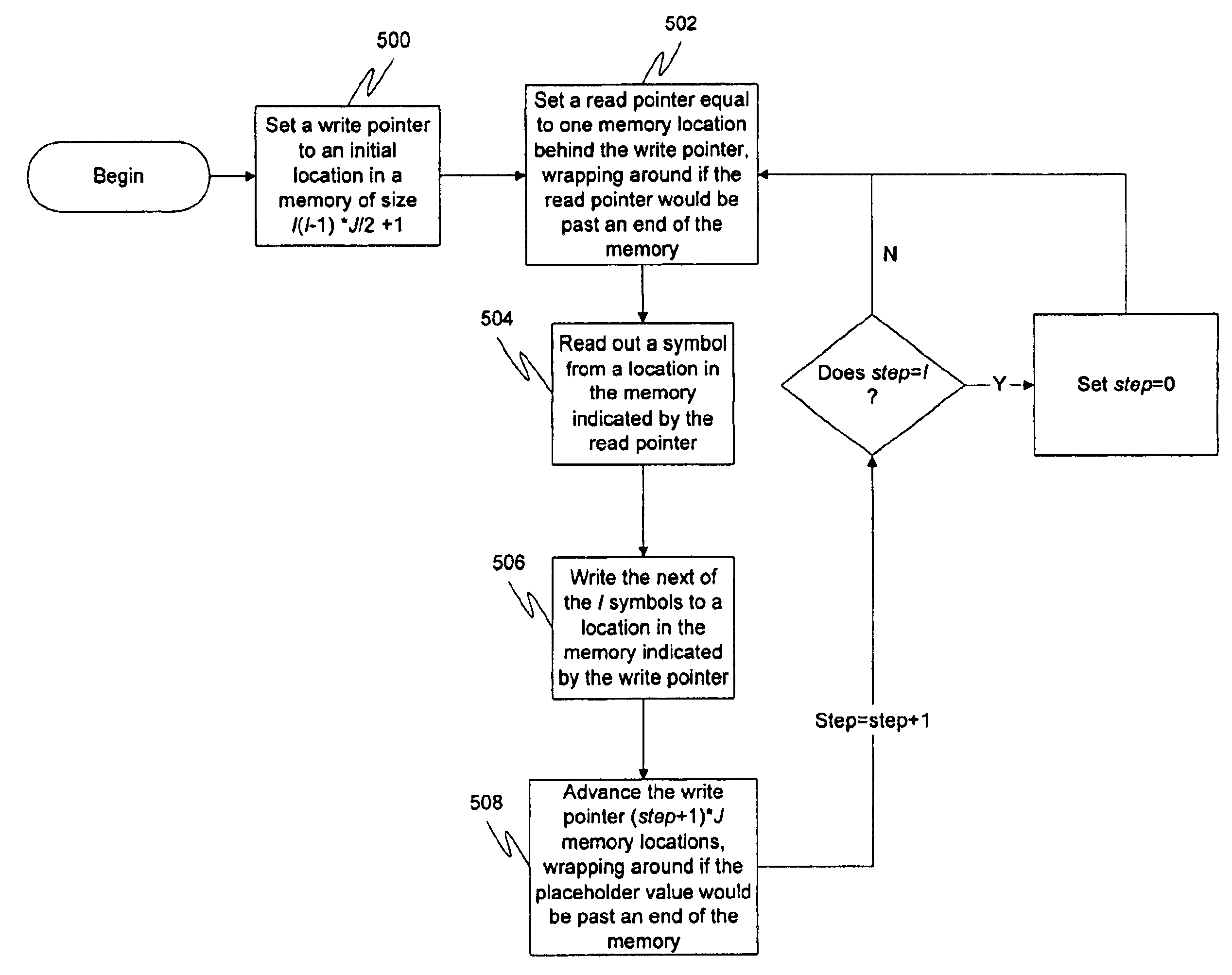
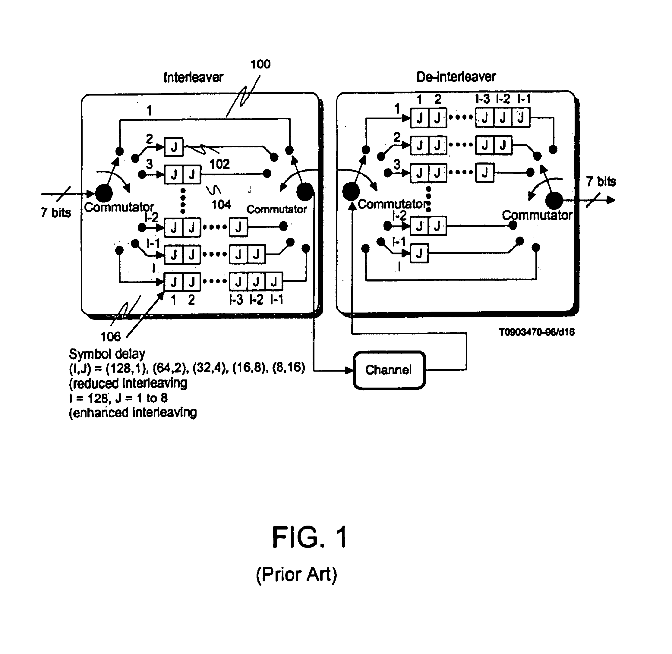
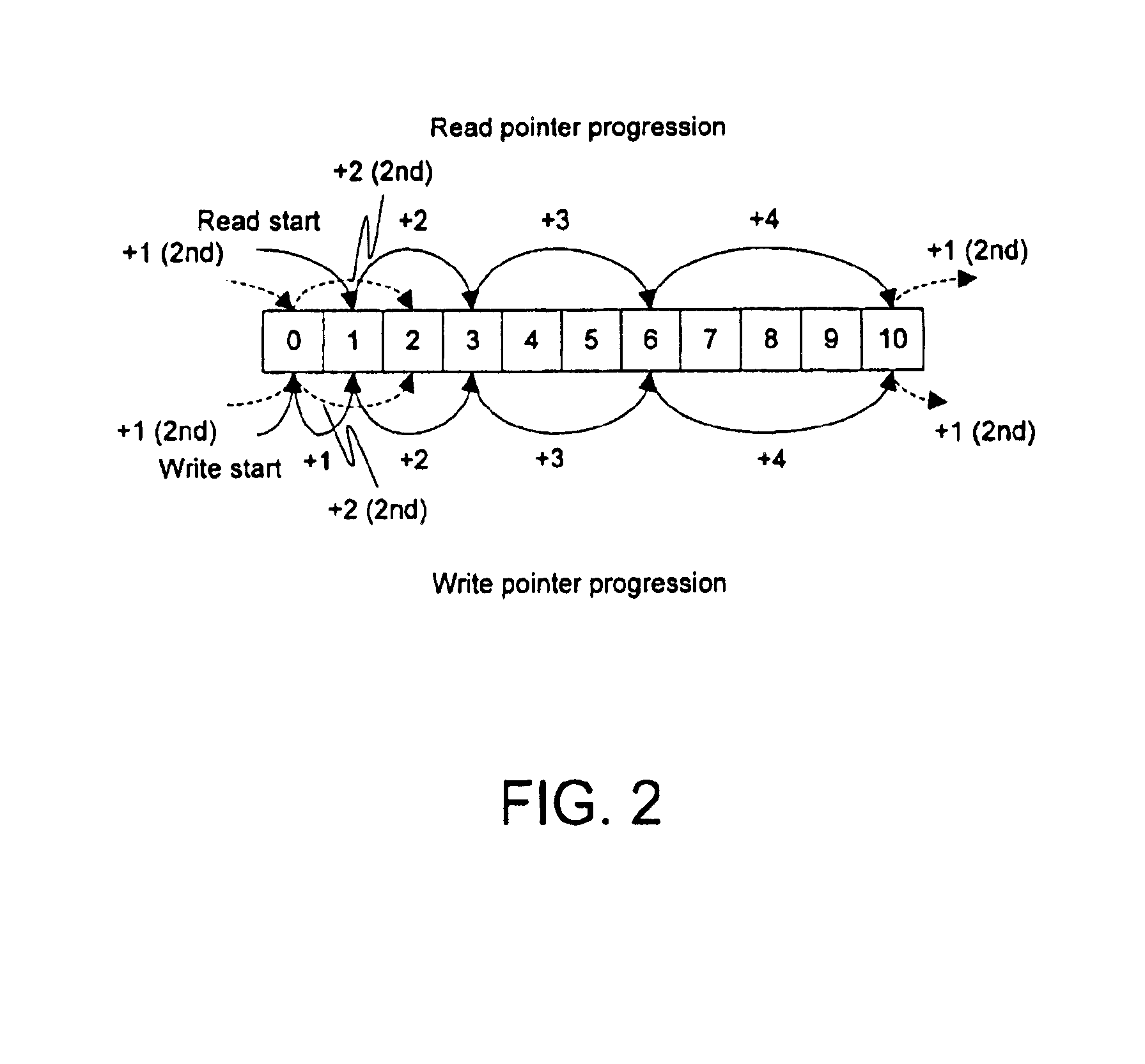
Embodiments of the present invention are described herein in the context of a system and method for remote performance analysis and optimization of computer systems. Those of ordinary skill in the art will realize that the following detailed description of the present invention is illustrative only and is not intended to be in any way limiting. Other embodiments of the present invention will readily suggest themselves to such skilled persons having the benefit of this disclosure. Reference will now be made in detail to implementations of the present invention as illustrated in the accompanying drawings. The same reference indicators will be used throughout the drawings and the following detailed description to refer to the same or like parts.

In the interest of clarity, not all of the routine features of the implementations described herein are shown and described. It will, of course, be appreciated that in the development of any such actual implementation, numerous implementation-sp...


PUM


Abstract

Memory may be partitioned into ever-sliding FIFOs. Each of the FIFOs may be stacked end-to-end in memory with the oldest data at the base offset and the newest at the end (or vice-virsa). Each symbol, the pointer may be incremented (modulo the set size) by an appropriate amount (typically J more than for the previous symbol). After each set, the pointers may be incremented by J more than the previous increment and the process starts over, wrapping around the memory if the end of the memory is reached. After a preset number of symbols, the process may restart from an increment of J. Alternatively, the pointers may be decremented rather than incremented. Thus, the newest symbol cannibalizes the memory position vacated by the oldest symbol in the current FIFO, causing the FIFOs to “slide”, providing for a very efficient and reliable use of memory for error-correcting code interleaving.

Description

FIELD OF THE INVENTIONThe present invention relates to communications systems. More particularly, the present invention relates to a solution for interleaving error-correcting code.BACKGROUND OF THE INVENTIONWhen digital data is transmitted over what could potentially be a noisy channel, it is important to have a means of recovery against at least a limited number of errors. These errors may be introduced into a data stream by noise or other environmental factors. The process of recovering data having errors is known as error-correction. Error-correction is generally accomplished by adding a number of redundant pieces of data to a string of data being communicated. When a receiver attempts to reconstruct the original message sent, it may begin by examining a possibly corrupted version of the encoded message, and then makes a decision as to which data (if any) to correct.The set of all possible encoded messages is known as an error-correcting code. Broadly, there are two types of err...

Claims


Application Information

Patent Timeline
Patent Type & Authority Patents(United States)
IPC IPC(8): H03M13/27H03M13/00
CPCH03M13/2732H03M13/2782H03M13/276
Inventor FANFELLE, ROBERT J.HUBRIS, ALEXANDER
Owner TERAYON COMM SYST
Why Eureka
Try Eureka