Traffic sign device

a technology of traffic signs and signs, which is applied in the direction of lighting support devices, instruments, roads, etc., can solve the problems of reducing contaminating the post “p”, and affecting the service life of traffic signs, so as to achieve simple operation, facilitate installation, and simplify the effect of installation

Inactive Publication Date: 2005-01-11
HYNYANG FRAME CO LTD
View PDF23 Cites 18 Cited by
  • Summary
  • Abstract
  • Description
  • Claims
  • Application Information

AI Technical Summary

Benefits of technology

By the traffic sign device according to the present invention, a sign board is easily installed on a post by a simple operation of placing the post clamp on a post and joining the movable pipe fixed to the sign board into the socket pipe fixed to the post clamp, by bolts and nuts, an operation of installing the sign board is very much simplified.
Further, since the sign board is formed into a drum shape, and the joint portion relative to the support bar is positioned behind the sign board, the coupling part in the sign board is effectively prevented

Problems solved by technology

However, since the conventional structure for supporting traffic sign has the guide rails 4 attached to the rear side of the sign board 3 and the U-shaped bands 5 for coupling the sign board to the hanger 2, the U-shaped bands 5 must be fastened by the bolts 7 and nuts 8 at both its ends after assembling the bolts 7 in the guide rails 4, an operation of establishing the traffic sign on the post “P” is considerably complicated.
Though the respective components are manufactured by iron material and then coated with paint, the components are apt to be oxidized and corroded due to aging of the paint at their coupled portions, thereby causing contamination of the post “P” and reduction of service life of the traffic sign.
Furthermore, since the sign board 3 is form

Method used


Image

  • Traffic sign device
  • Traffic sign device
  • Traffic sign device

Examples


second embodiment

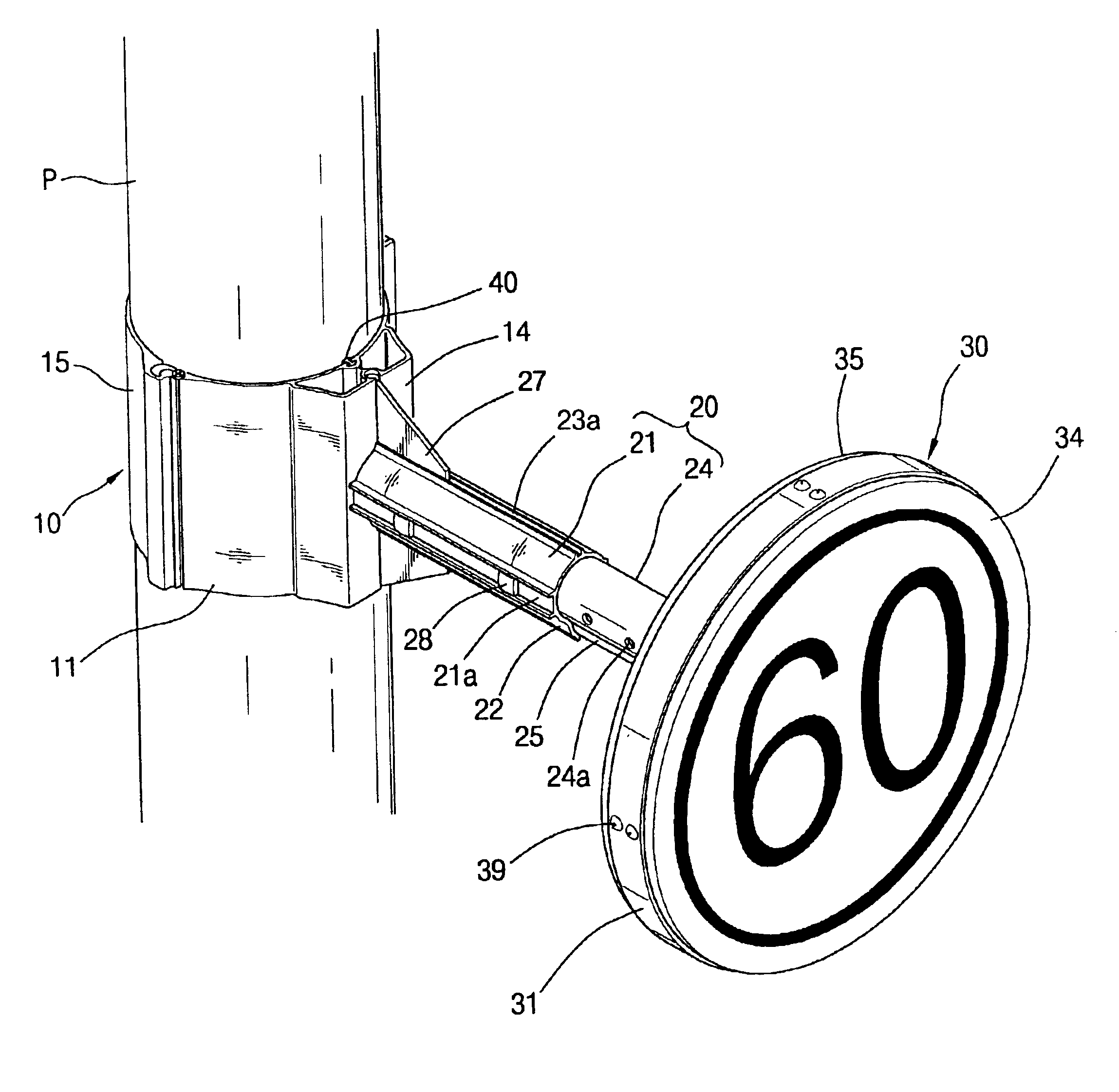
Referring again to FIG. 9 to FIG. 10 of the drawings, there is shown the traffic sign device according to the present invention.

Similar to the first embodiment, the traffic sign device includes a post clamp 10 mounted on a post “P”, a support bar 20 radially joined to an outer surface of the post clamp 10 to be horizontally positioned, a sign board 60 mounted on free end of the support bar 20 to exhibit a road sign, and a coupling unit 62 for connecting the sign board 60 to the support bar 20.

In this embodiment, since the configuration of the post clamp 10 and the support bar 20 is exactly same as those of the first embodiment, the details will be omitted for brevity's sake by denoting the same components by the same reference number.

The sign board 60 is formed into a single plane plate having a skirt 61 inwardly extended at a desired width. The skirt 61 is intended to increase the structural strength of the sign board 60 and to properly shield the exposure of the coupling unit 62 j...


PUM


Abstract

A traffic sign device is disclosed. The device includes a post clamp having at least two arched clamping bands, which are hingedly coupled to each other at their adjacent ends and joined to each other by a fastening element at their free ends to be installed on a post; a support bar having a socket pipe radially joined to an outer surface of one of the clamping bands, the socket pipe being axially provided with at least a joint hole, and a movable pipe slidably inserted into the socket pipe, the movable pipe being axially provided with a plurality of spaced holes in order to set the outward extent of the movable pipe; a sign board having an annular band frame with its peripheral edges being formed coupling grooves, and a front and rear covers with a skirt formed along the peripheral edge of the covers to be fitted into the coupling grooves; and a coupling unit for concentrically coupling the free end of the movable pipe to the center portion of the rear cover. The device allows the sign board to be easily installed on the post by a simple operation. As the sign board is formed into a drum shape, the coupling part behind the sign board is effectively shielded from a view. The invention ensures favorable appearance of the sign device as well as its extended service life.

Description

BACKGROUND OF THE INVENTION1. Field of the InventionThe present invention relates to a traffic sign device installed on a roadside post to exhibit various restrictions, directions, and warning on the road for safety of traffic or to show information regarding street names or location of a destination for convenience of drivers or pedestrians, and more particularly to a structure of a traffic sign device which allows a sign board to be easily attached to a post and which improves durability of the sign device with an acceptable appearance.2. Description of the Prior ArtIn general, various road signs are installed on roadsides or above roads to show drivers and pedestrians information relating to a road and cautions in order to assure safety and smooth driving conditions, and which are further intended to provide drivers with information relating to use of a road to preserve the structure of the road.Such a road sign is manufactured into a designated shape and size and installed accor...

Claims


Application Information

Patent Timeline
IPC IPC(8): G09F7/18E01F9/623E01F9/658E01F9/677E01F9/681E01F9/696
CPCG09F15/0037G09F7/18G09F2007/1804
Inventor KIM, YONG SOO
Owner HYNYANG FRAME CO LTD
Why Eureka
Try Eureka