Attachment for a medical device

a technology for medical devices and needles, applied in the direction of catheters, liquid handling, packaging goods types, etc., can solve the problems of needle carriers that cannot be easily disengaged, structures that cannot withstand the forces of normal use, and dispensing containers that are not readily available or practical

Inactive Publication Date: 2005-01-11
BECTON DICKINSON & CO
View PDF115 Cites 80 Cited by
  • Summary
  • Abstract
  • Description
  • Claims
  • Application Information

AI Technical Summary

Benefits of technology

A fluid transfer adapter for use with a syringe barrel having an inside surface defining a chamber, an open proximal end, an open distal end including a collar having adapter engaging structure and a distally-facing frusto-conically shaped surface comprises a hub having a proximal end, a distal end and a conduit therethrough. A proximally-facing frusto-conically shaped surface on the hub is provided for mating with the frusto-conically shaped surface on the syringe barrel. Means for threadably engaging

Problems solved by technology

However, there are areas of medical practice, such as emergency rooms, where disposal containers may not be readily available or practical, and where products having self-contained safety features are desirable.
Many prior art retractable needle syringe designs when made with sufficient strength to withstand the forces of normal use have a needle carrier which cannot be easily disengaged.
On the other hand, easy disengagement of the needle or the needle carrier can lead to a structure which may not withstand the forces of normal use.
In addition, retractable needle syringes require a two-handed withdrawal procedure which increases the difficulty of use.
The retracting needle syringes have similar design problems as those recited hereinabove for retractable needle syringes.
Some of the prior art retracting needle syringes use plugs

Method used


Image

  • Attachment for a medical device
  • Attachment for a medical device
  • Attachment for a medical device

Examples


Embodiment Construction

While this invention is satisfied by embodiments in many different forms, there are shown in the drawings and will herein be described in detail, preferred embodiments of the invention with the understanding that the present disclosure is to be considered exemplary of the principles of the invention and not intended to limit the scope of the invention to the embodiments illustrated. The scope of the invention will be measured by the appended claims and their equivalents.

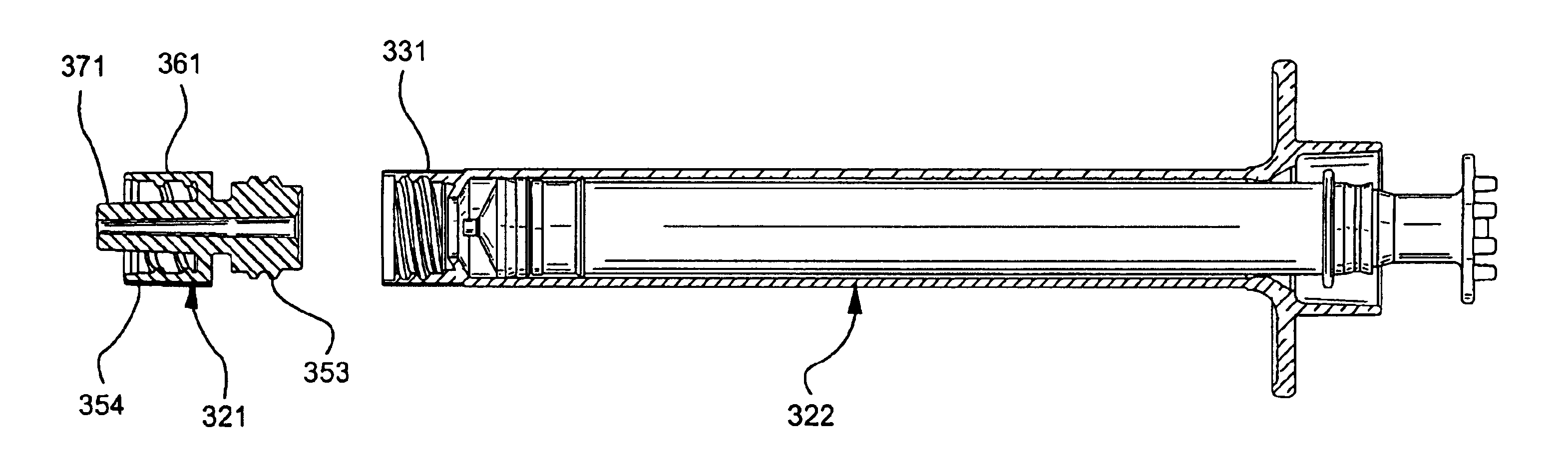
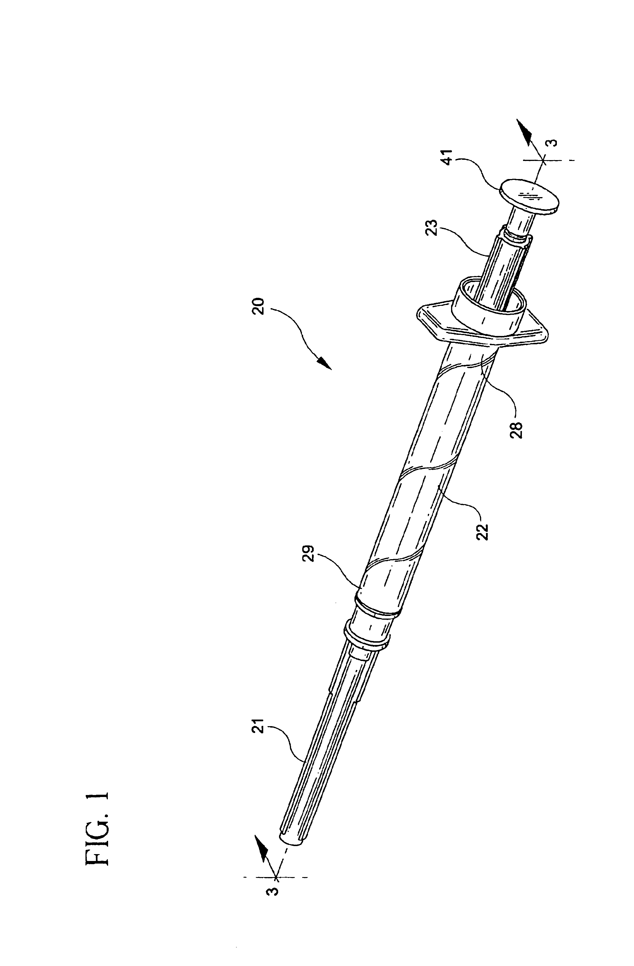
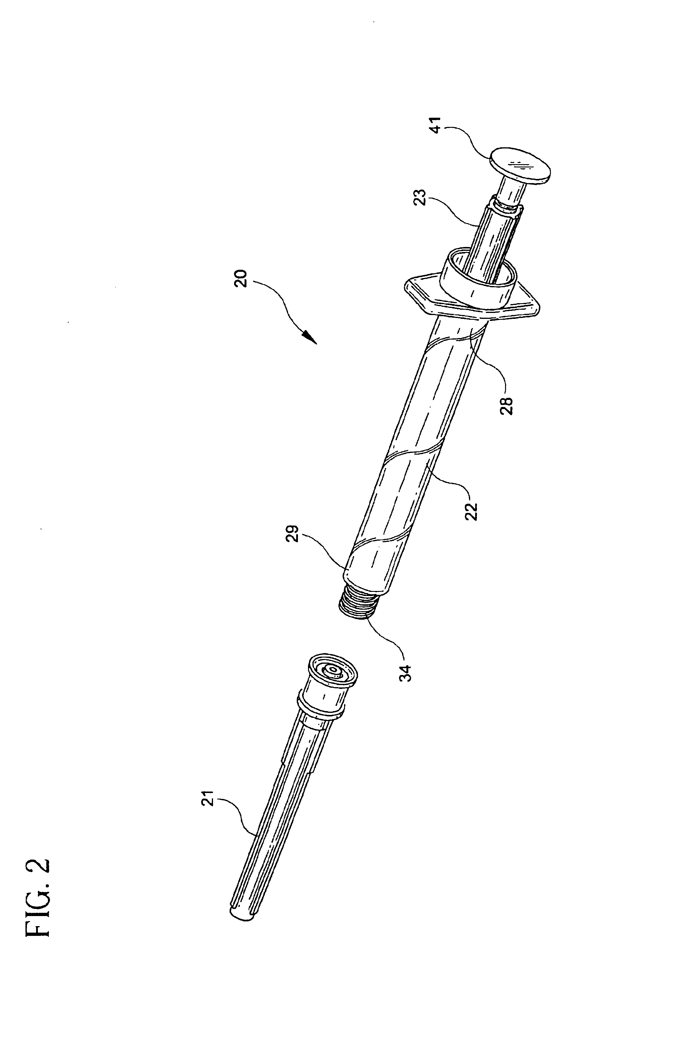
Referring to FIGS. 1-11, an operable retracting needle syringe 20 includes a retracting needle assembly 21, a syringe barrel 22 and a plunger 23. The barrel includes an inside surface 25 defining a chamber 27, an open proximal end 28 and an open distal end 29 including a cylindrical collar 31 having an outside surface 32 and an inside surface 33.

The plunger is slidably positioned in fluid-tight engagement with the inside surface of the barrel. The plunger includes a proximal portion 37 having a distal end 38 with an ...


PUM

PropertyMeasurementUnit
Lengthaaaaaaaaaa
Lengthaaaaaaaaaa
Angleaaaaaaaaaa

Abstract

A fluid transfer adapter for use with a syringe barrel having a collar with adapter engaging structure and a distally-facing frusto-conically shaped surface is disclosed. The adapter includes a hub having a proximally-facing frusto-conically shaped surface for mating with the frusto-conically shaped surface on the barrel, structure for threadably engaging the hub to the collar of the barrel so that the frusto-conically shaped surface of the hub contacts the frusto-conically shaped surface of the barrel to prevent liquid flow between the surfaces and a fluid transfer having a passageway therethrough, connected to the distal end of the hub so that the lumen is in fluid communication with a conduit in the hub. The passageway includes a frusto-conically shaped edge that aligns with the frusto-conically shaped edge of the barrel, when the adapter is connected to the barrel, thereby reducing waste space.

Description

FIELD OF THE INVENTIONThe present invention relates to syringes and needle assemblies. More particularly, the present invention relates to a syringe and needle assembly having structure allowing for the automatic withdrawal of the needle cannula into the syringe barrel after use and a method for making the needle assembly. The present invention also relates to adapters for use with such syringes.BACKGROUNDIn recent years there has developed an increased concern regarding the transfer of disease, infection or the like to syringe users and healthcare professionals who accidentally or through negligent handling, stick themselves with hypodermic needles while disposing of used hypodermic needle containing products. In many areas in a hospital, where needle cannula products are used, disposal bins are provided so that a syringe or other needle cannula product may be immediately discarded in a safe rigid container. However, there are areas of medical practice, such as emergency rooms, whe...

Claims


Application Information

Patent Timeline
IPC IPC(8): A61M5/32A61M5/00A61M5/34A61M5/50A61MA61M25/00
CPCA61M5/3234A61M5/002A61M5/3202A61M5/344A61M5/345A61M5/349A61M5/502A61M5/508A61M5/3134A61M5/347
Inventor CAIZZA, RICHARDSMITH, CHADPAWLOWSKI, JOHN
Owner BECTON DICKINSON & CO
Why Eureka
Try Eureka