Tubing annulus valve

a tubing annulus and check valve technology, applied in the direction of quarries, well accessories, separation processes, etc., can solve the problems of time-consuming, inability to test the check valve readily, and the inability to have such a completion riser available in the drilling vessel, etc., to achieve the effect of improving durability

Inactive Publication Date: 2005-01-11
VETCO GRAY
View PDF15 Cites 68 Cited by
  • Summary
  • Abstract
  • Description
  • Claims
  • Application Information

AI Technical Summary

Benefits of technology

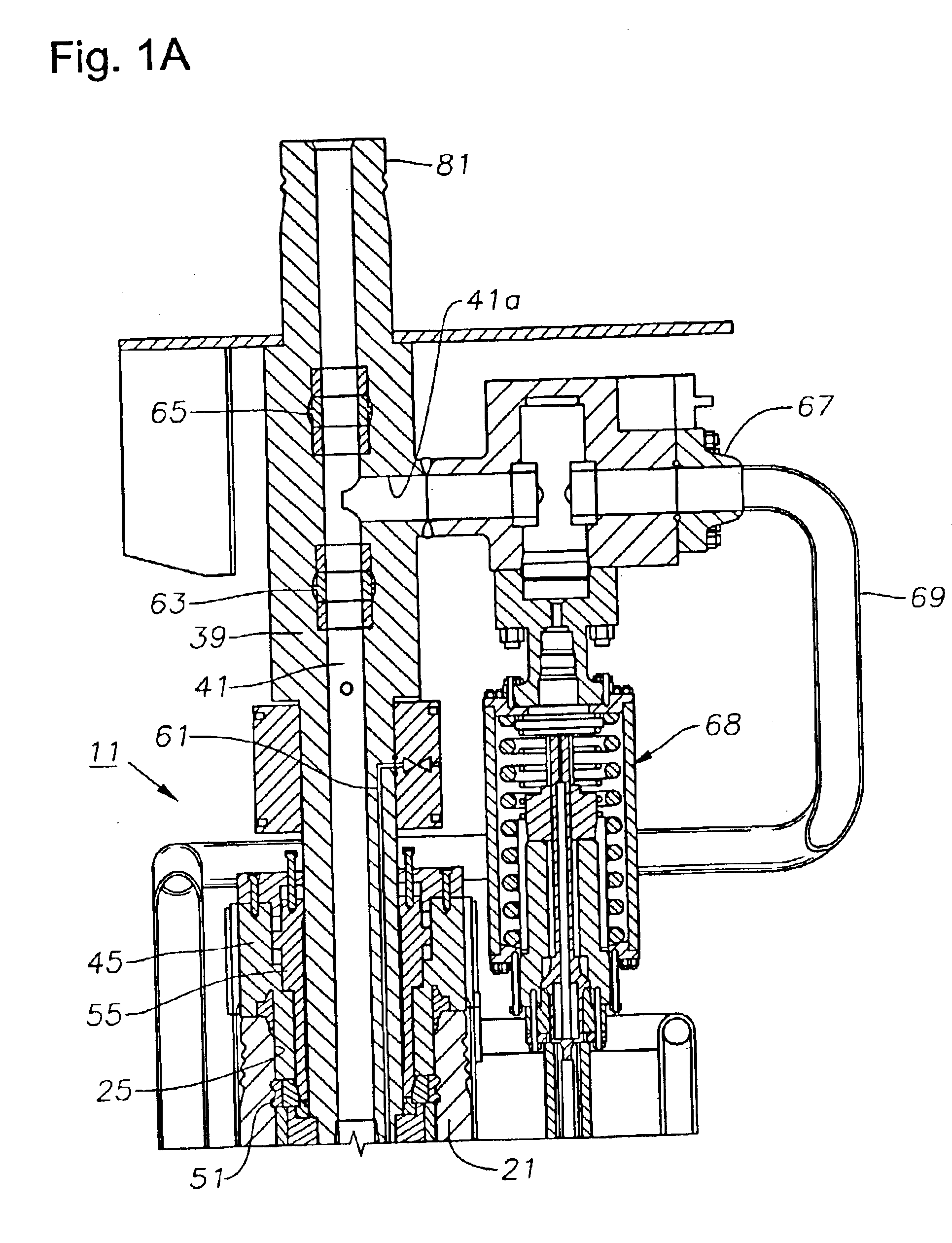
The tubing hanger also preferably has an offset tubing annulus passage. The tubing annulus passage communicates the tubing annulus with a void space surrounding the isolation tube above the tubing hanger. A tubing annulus valve is located in the upper end of the tubing annulus passage for selectively blocking communication between the void space and the tubing annulus passage. The tubing annulus valve of the preferred embodiment has a primary dynamic metal-to-metal seal for enhanced durability.
The tubing annulus valve includes a movable member that moves between an open position and a closed position. Preferably, the movement is vertical, with t

Problems solved by technology

It is time consuming, however to assemble and run a dual string completion riser.
Also, drilling vessels may not have such a completion riser available, requiring one to be supplied on a rental basis.
A disadvantage is that one can

Method used


Image

  • Tubing annulus valve
  • Tubing annulus valve
  • Tubing annulus valve

Examples


Embodiment Construction

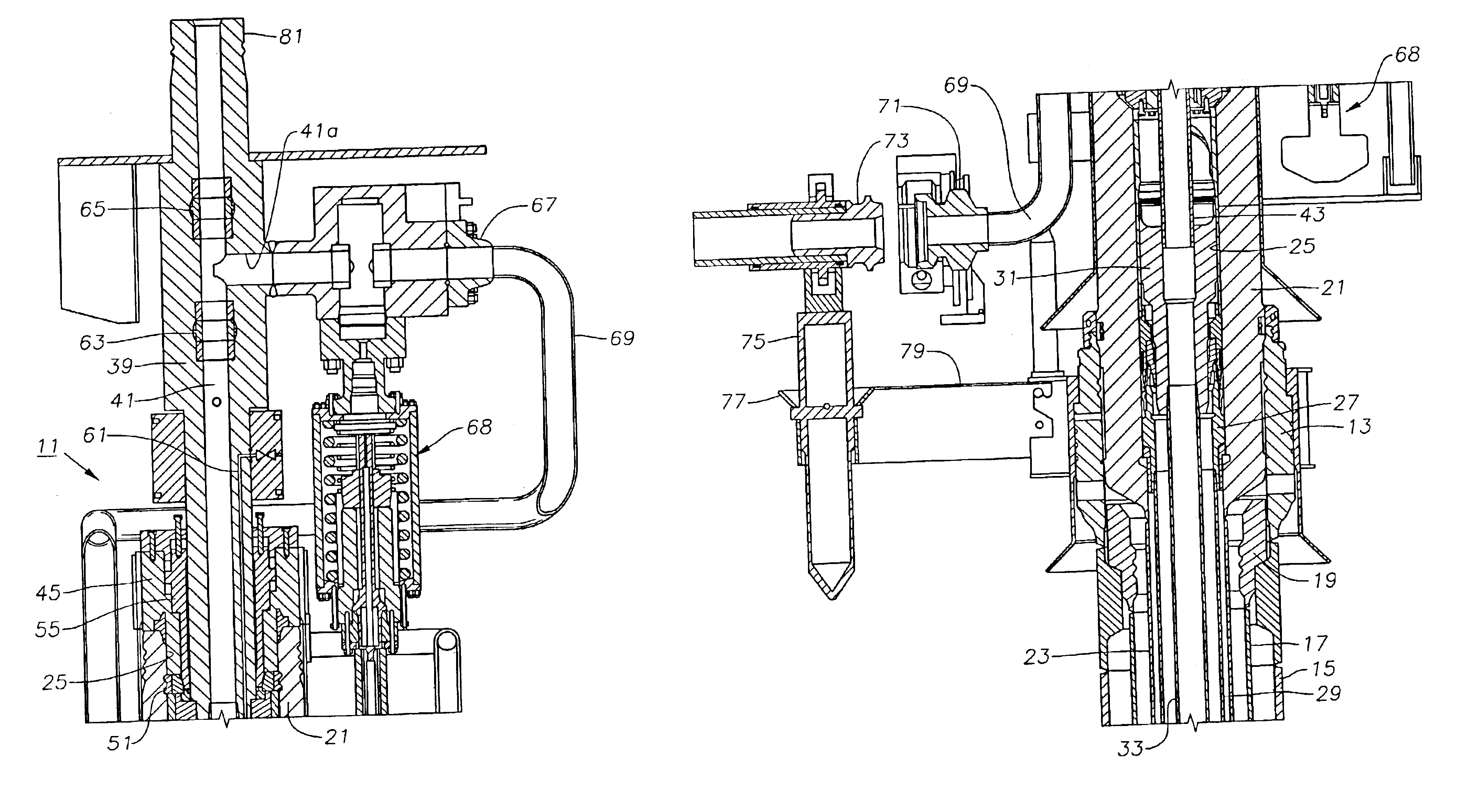
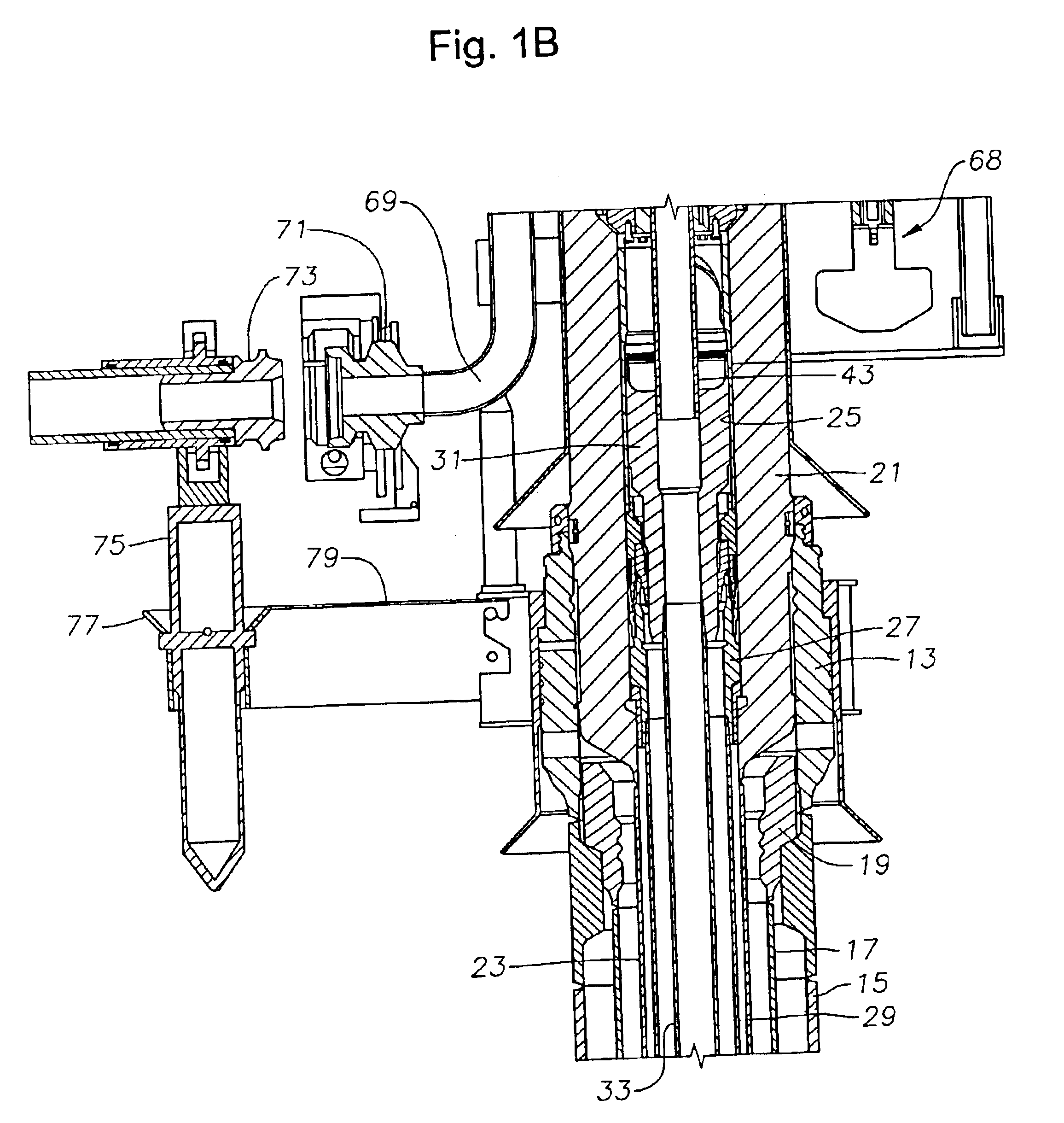
Referring to FIG. 1B, a lower portion of a wellhead assembly 11 includes an outer or low pressure wellhead housing 13 that locates on the sea floor and is secured to a string of large diameter conductor pipe 15 that extends into the well. In this embodiment, a first string of casing 17 is suspended on a lower end of outer wellhead housing 13 by a hanger 19. However, casing 17 and hanger 19 are not always suspended from the outer wellhead housing 13 and can be eliminated in many cases.

An inner or high pressure wellhead housing 21 lands in and is supported within the bore of outer wellhead housing 13. Inner wellhead housing 21 is located at the upper end of a string of casing 23 that extends through casing 17 to a greater depth. Inner wellhead housing 21 has a bore 25 with at least one casing hanger 27 located therein. Casing hanger 27 is sealed within bore 25 and secured to the upper end of a string of casing 29 that extends through casing 23 to a greater depth. In this embodiment, a...


PUM


Abstract

A subsea wellhead assembly has a tubing hanger with a tubing annulus passage and a production passage. A metal-sealing shuttle valve is mounted in the tubing hanger for blocking upward flow through the tubing annulus passage. The shuttle valve has a retention mechanism that prevents the shuttle from moving to the open position when fluid pressure is applied from above. The retention mechanism is released by the running tool after testing has been completed, causing the shuttle to close. The tree has an engaging member that can be stroked downward into the tubing hanger annulus passage to move the shuttle valve to the open position for communicating with the annulus.

Description

FIELD OF THE INVENTIONThis invention relates in general to subsea wellhead systems and in particular to a tubing hanger with a tubing annulus passage and a tubing annulus valve with features to facilitate testing.BACKGROUND OF THE INVENTIONA typical subsea wellhead assembly has a high pressure wellhead housing supported in a lower pressure wellhead housing and secured to casing that extends into the well. One or more casing hangers land in the wellhead housing, the casing hanger being located at the upper end of a string of casing that extends into the well to a deeper depth. A string of tubing extends through the casing for production fluids. A Christmas or production tree mounts to the upper end of the wellhead housing for controlling the well fluid. The production tree is typically a large, heavy assembly, having a number of valves and controls mounted thereon.One type of tree, sometimes called “conventional”, has two bores through it, one of which is the production bore and the ...

Claims


Application Information

Patent Timeline
IPC IPC(8): B01D17/00B01D17/02C02F1/48E21B34/00E21B34/04E21B33/03E21B33/038E21B43/34E21B43/36E21B43/40C02F1/40
CPCB01D17/0211E21B33/038E21B34/04E21B43/36E21B43/40C02F1/48B01D17/00B01D17/0208B01D17/0217B01D17/045B01D17/06B01D17/0214C02F1/40C02F2101/32C02F2103/06C02F2103/10
Inventor FENTON, STEPHEN P.HED, JON EROGERS, ROBERT N.
Owner VETCO GRAY
Why Eureka
Try Eureka