Airbag module attachment arrangement

a technology for airbag modules and attachment arrangements, which is applied in the directions of transportation and packaging, pedestrian/occupant safety arrangements, vehicular safety arrangements, etc., can solve the problems of complicated attachment of airbag modules, complicated assembly and disassembly, and easy installation of airbag modules

Inactive Publication Date: 2005-01-11
KEY SAFETY SYST
View PDF11 Cites 20 Cited by
  • Summary
  • Abstract
  • Description
  • Claims
  • Application Information

AI Technical Summary

Benefits of technology

The switch assemblies engage the airbag cover and are located proximate the steering wheel spokes. An aesthetically pleasing fit between the cover and the molded armature is thereby provided. Any separation line is minimized while allowing horn activation by a light pressure upon the airbag cover. A clearance between the airbag module engagement member and each corresponding airbag module member assures that there is no interference, which may result in undesirable noise and or vibration.

Problems solved by technology

The airbag module must be easily installed yet difficult to remove by an unauthorized person.
Attachment of the airbag module is further complicated by the requirement that a horn actuator be mounted to the steering wheel assembly.
However, mounting of the airbag module is typically with threaded fasteners, which may complicate assembly and disassembly.
Further, as the thin film actuator is mounted below the airbag cover and above the airbag module, replacement of the actuator may be complicated and time intensive should the thin film actuator fail.
Disadvantageously, the robust design of the switch assembly results in a complicated and expensive switch assembly.
This may be rather inconvenient.
Commonly, this results in a noticeable separation line or gap between the airbag module and the steering wheel assembly.

Method used


Image

  • Airbag module attachment arrangement
  • Airbag module attachment arrangement
  • Airbag module attachment arrangement

Examples


Embodiment Construction

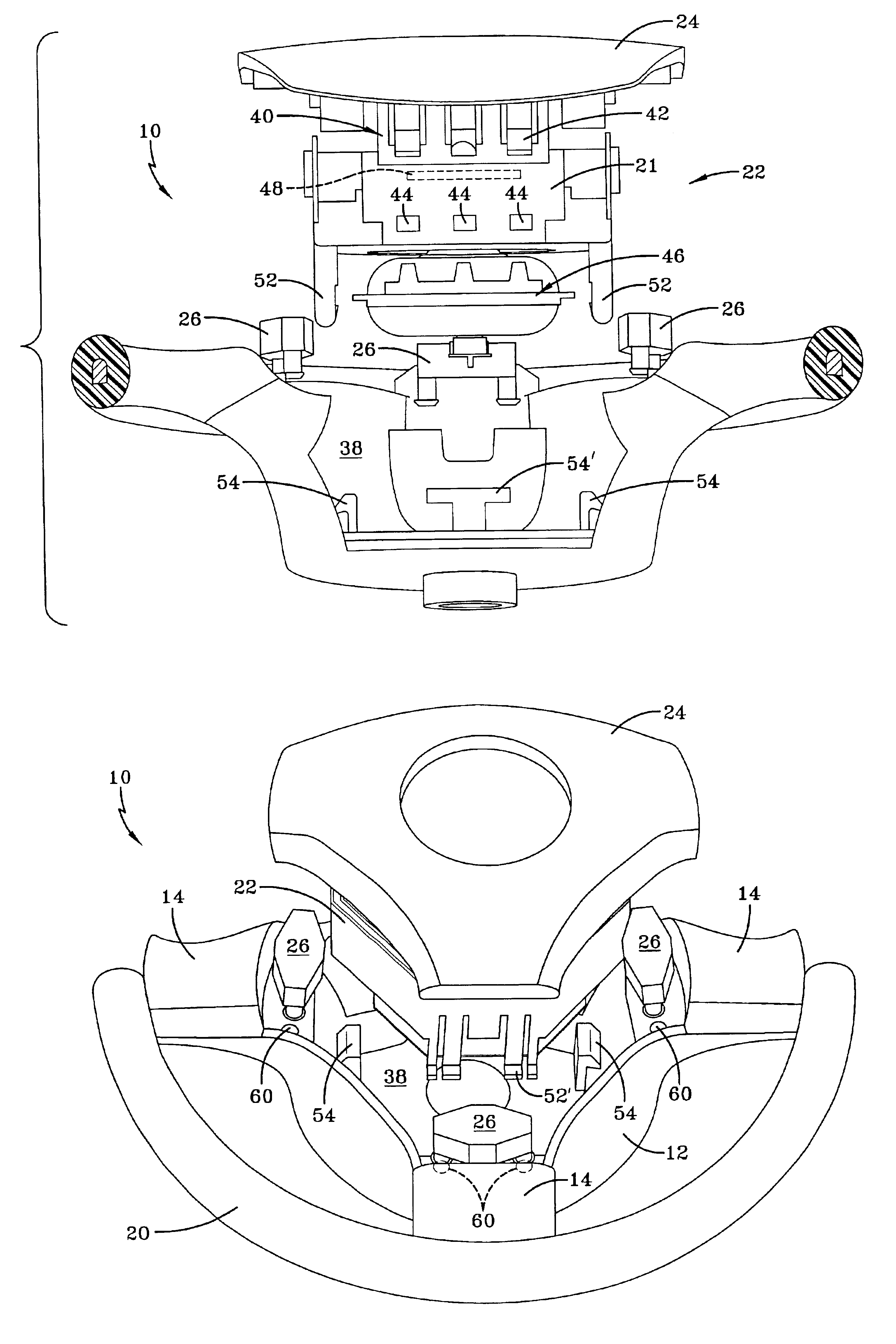
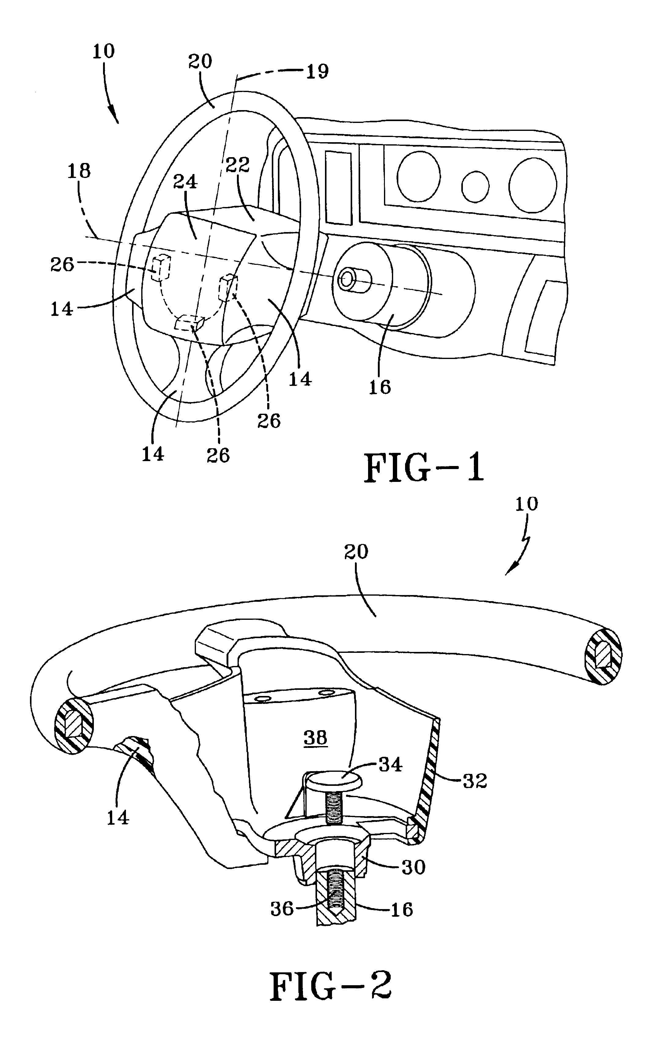
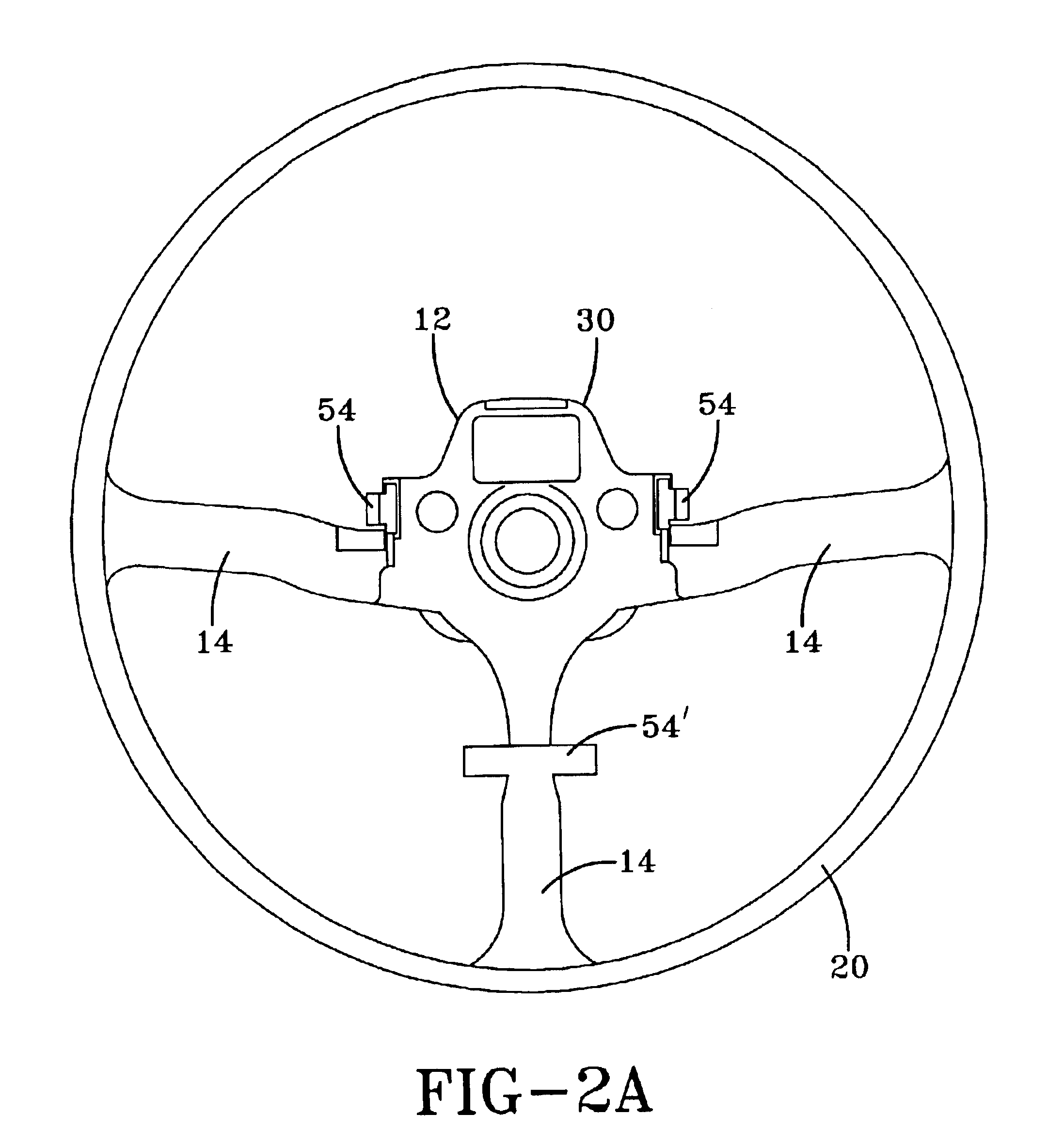
FIG. 1 illustrates a vehicle steering wheel assembly 10 positioned next to the steering column 16. The steering wheel assembly 10 includes a central hub portion 12 (FIG. 2A) with outwardly extending spokes 14. The hub portion 12 has an axis 18 substantially perpendicular to the hub portion 12 and coaxial to the steering column 16. An essentially circular rim 20 is connected to the hub portion 12 by the spokes 14. The spokes 14 are preferably arranged from the central hub portion 12 to the rim 20 at 90, 180 and 270-degree positions. In other words, the spokes 14 are arranged at 3, 6, and 9 o'clock positions where 12 o'clock is the top of the rim 20 when viewed from the drivers position. One skilled in the art appreciates that the steering wheel assembly 10 could have any number of spokes and the spokes could be arranged in different positions.

Referring to FIG. 2, the steering wheel assembly 10 includes a metallic steering wheel armature 30, which is overmolded with a non-metallic mat...


PUM


Abstract

A vehicle steering wheel assembly having a molded armature with outwardly extending spokes for mounting on a steering column. Airbag engagement members extend from an airbag module housing to engage corresponding hub engagement members. The airbag module rests on a multiple of switch assemblies while the engagement members are separated by a clearance. The engagement members are only in contact if the airbag is fired. A clearance between each hub engagement member and each corresponding airbag engagement member assures that there is no interference that may result in undesirable noise or vibration.

Description

BACKGROUND OF THE INVENTIONThe present invention relates to an airbag module, and more particularly to an attachment arrangement, which supports the airbag module upon a plurality of switches while providing primary airbag module retention.It is well known to provide an airbag module in a vehicle at such locations as in a steering wheel, a dashboard, a seat, door panel or other location. A typical airbag module includes an airbag inflator positioned adjacent an airbag to discharge an inflator gas to inflate the airbag upon sensing certain predetermined vehicle conditions.The airbag module is commonly formed as a separate and independent unit from the vehicle. The airbag module must be easily installed yet difficult to remove by an unauthorized person. Attachment of the airbag module is further complicated by the requirement that a horn actuator be mounted to the steering wheel assembly. Typically, the horn is triggered by pressure applied to a portion of an airbag cover.In one known...

Claims


Application Information

Patent Timeline
Patent Type & Authority Patents(United States)
IPC IPC(8): B60R21/20B60Q5/00B60R16/02B60R16/027B60R21/203B62D1/04
CPCB60R21/2037B60Q5/003H01H13/02
Inventor XU, XIAOPINGLUO, JASONROSS, HUBERTMUNSCH, DETLEFRIDOLFI, ADOLFOGIRARDI, FEDERICOTESTA
Owner KEY SAFETY SYST
Why Eureka
Try Eureka