

Transport apparatus and vacuum processing system using the same
- Summary
- Abstract
- Description
- Claims
- Application Information
AI Technical Summary
Benefits of technology
Problems solved by technology
Method used
Image

Examples
Embodiment Construction
Preferred embodiments of the present invention will be described in detail below with reference to the accompanying drawings.
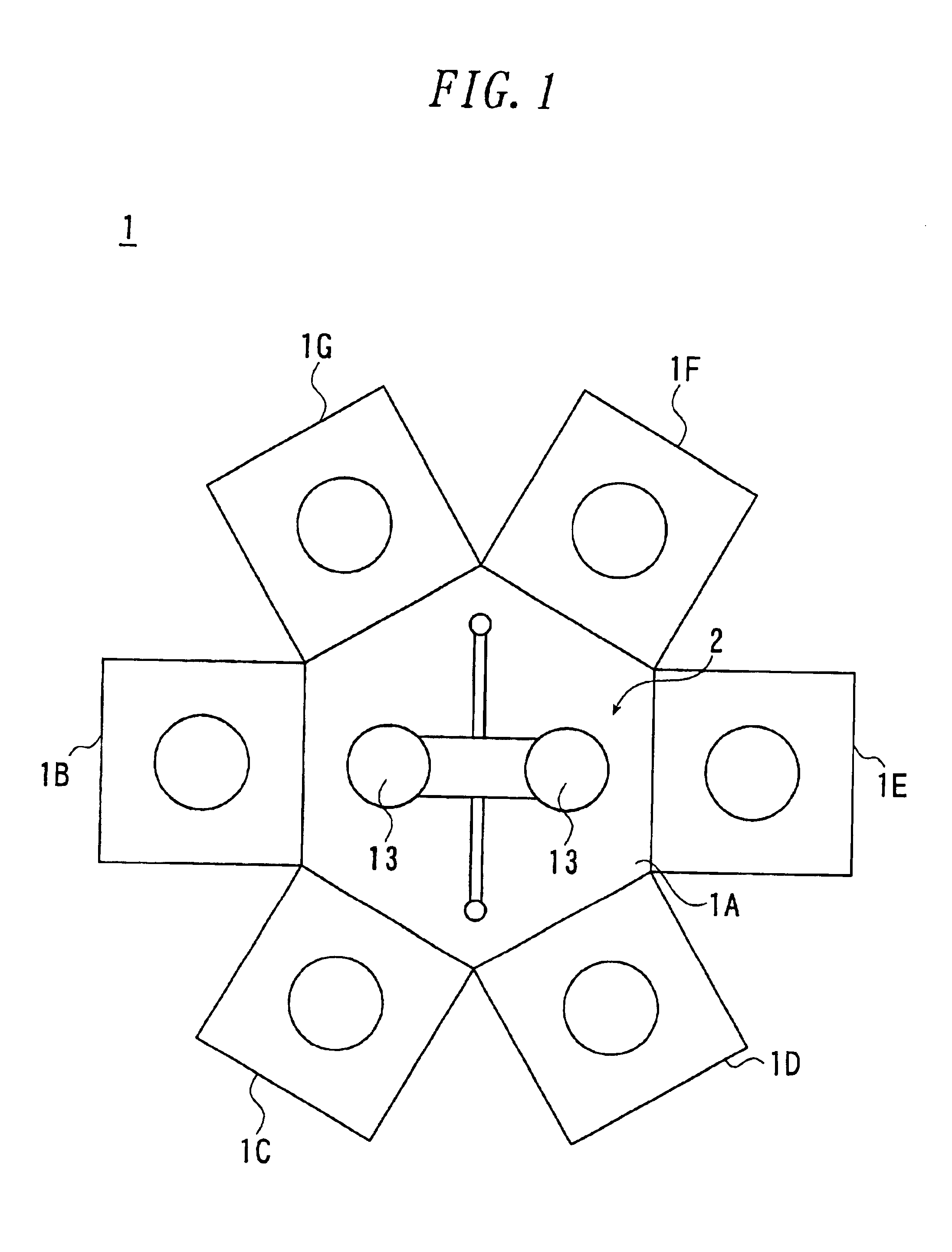
FIG. 1 shows a schematic illustration of a vacuum processing system according to the present invention.
The vacuum processing system 1 has a transport chamber 1A arranged at the center, and has a loading / unloading chamber 1B and first to fifth processing chambers 1C-1G arranged around the transport chamber 1A. The transport chamber 1A, loading / unloading chamber 1B, and first to fifth processing chambers 1C-1G are hermetically sealed and connected. Further, they can keep their vacuum atmospher separately.
In the conveying chamber 1A, a transport apparatus 2 according to the present invention is installed to bring a semiconductor wafer 13 into the loading / unloading chamber 1B and the first to fifth processing chambers 1C-1G and carrying it out from the chambers freely.
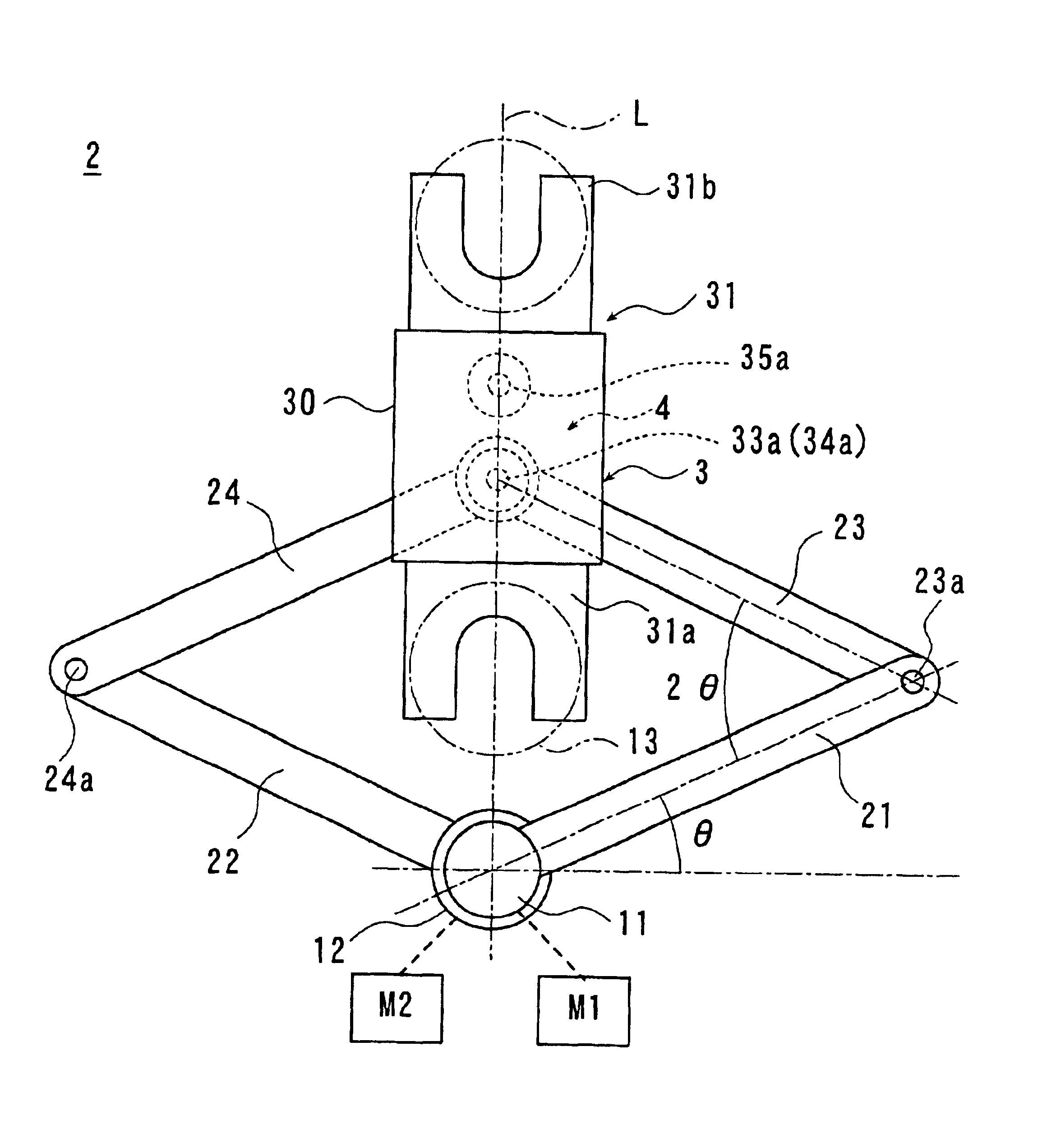
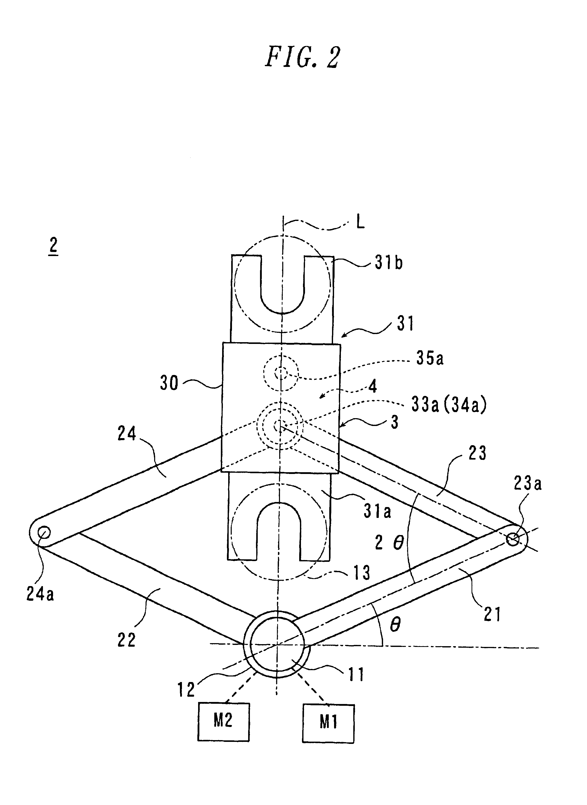
FIG. 2 is a plan view illustrating the configuration of an embodiment of the transport apparatus ...
PUM
 Abstract
Description
Claims
Application Information