Golf club head

a golf club and wing technology, applied in golf clubs, racket sports, sport apparatus, etc., can solve the problems of large flight distance, uniform thin-walled perimetric parts surrounding the central thick-walled portion, etc., and achieve high repulsion, great flight distance, and high resilience

Inactive Publication Date: 2005-01-11
YONEX CO LTD
View PDF5 Cites 103 Cited by
  • Summary
  • Abstract
  • Description
  • Claims
  • Application Information

AI Technical Summary

Benefits of technology

When a golf ball is hit at the central thick-walled portion of the face plate having the above construction, the springy property of the broad thin-walled portions at the perimeter thereof (in addition to the effect of lightweight metal with high resilience) imparts high repulsion to the ball, thus resulting in great flight distance.
Moreover, even when a golf ball is hit at a point off-set from the central thick-walled portion of the face plate, because the narrow rib exists at or near the point, and because the rib has high resilience due to its thickness being approximately of the same thickness as the central thick-walled portion, the ball flight deviation is prevented unlike the conventional case where a golf ball is hit at the boundary between the thick and thin portions.
Furthermore, the perimetric part surrounding the central thick-walled portion is not a uniformly thin-walled portion as in a conventional head. Instead, the surrounding part comprises the thin-walled portions which are reinforced by the narrow radial ribs so as to impart high strength to the overall face plate, thus preventing cracking from occurring between the central thick-walled portion and the thin-walled portions outside it.

Problems solved by technology

When a golf ball is hit at the central thick-walled portion of the face plate having the above construction, the springy property of the broad thin-walled portions at the perimeter thereof (in addition to the effect of lightweight metal with high resilience) imparts high repulsion to the ball, thus resulting in great flight distance.
Furthermore, the perimetric part surrounding the central thick-walled portion is not a uniformly thin-walled portion as in a conventional head.

Method used


Image

  • Golf club head
  • Golf club head

Examples


Embodiment Construction

A preferred embodiment of the present invention will be described hereinafter with reference to the accompanying drawings.

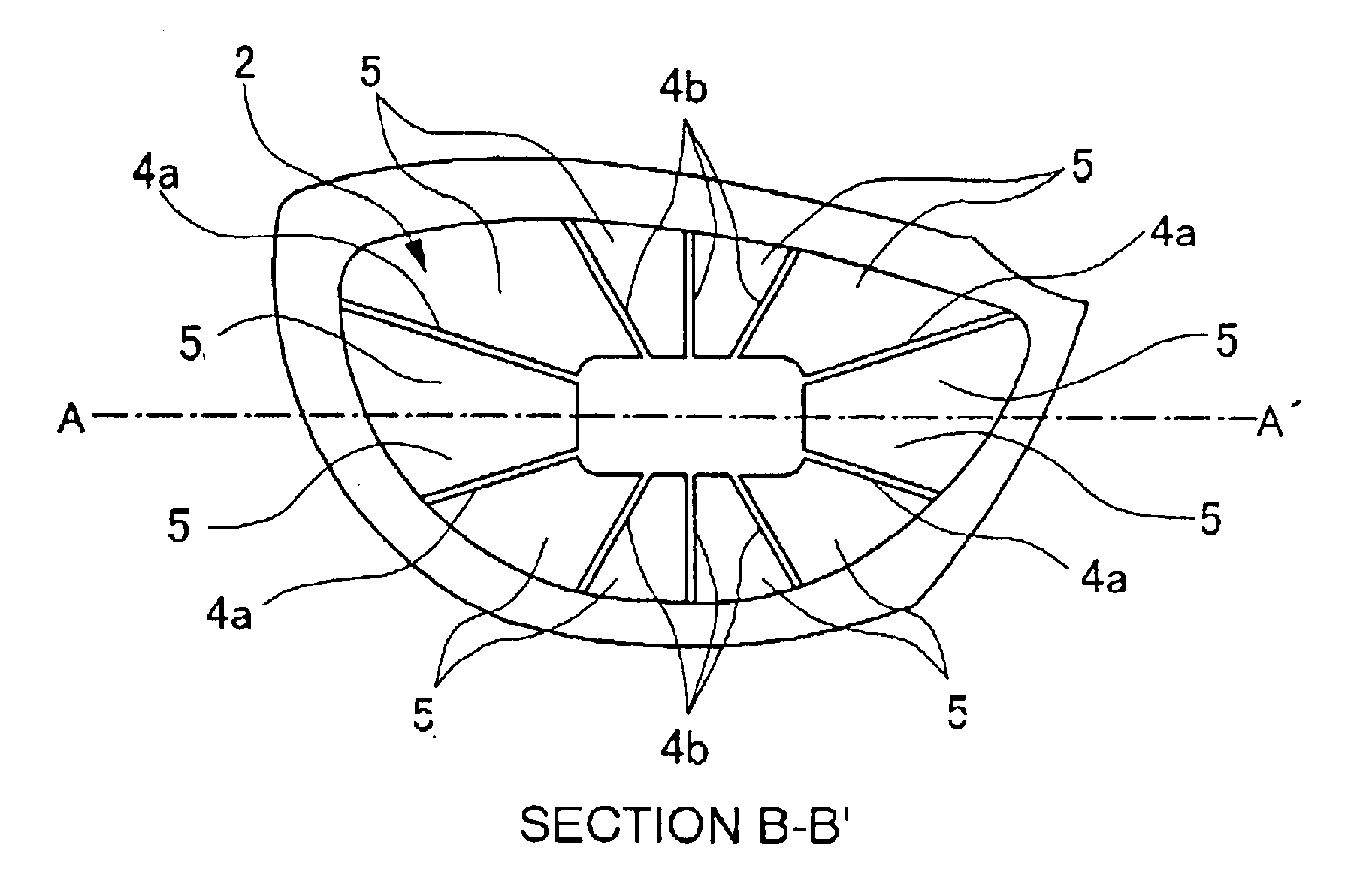
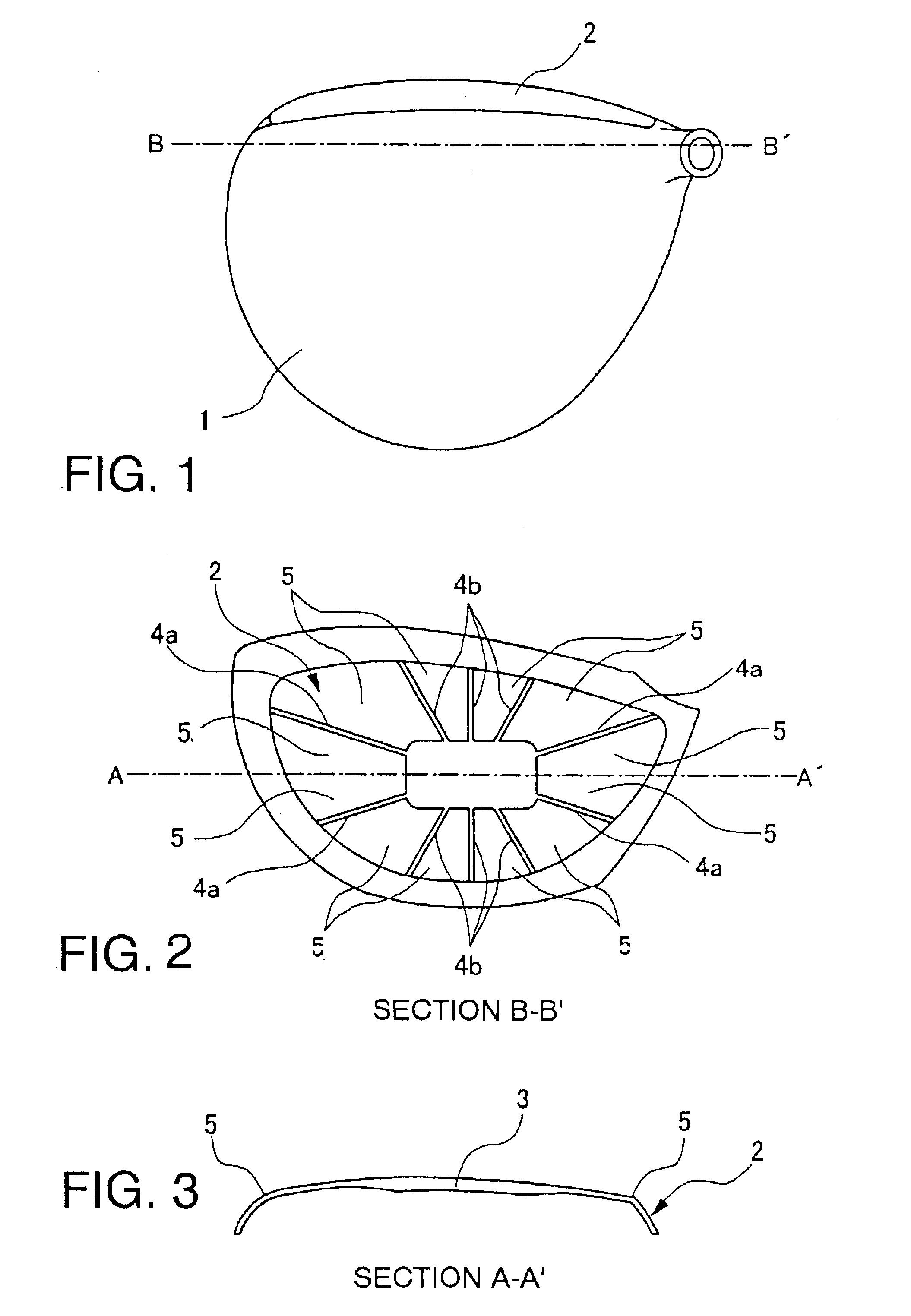
A golf club head of the present invention comprises a head body 1 and a face plate 2. The present invention will produce an excellent effect when applied to a club head having a head volume of 300 to 460 cc and a face area of 40 cm2.

At the center of the face plate 2 which is made of titanium alloy, is a rectangular central thick-walled portion 3, which has a horizontal side with a length about ⅓ the horizontal length of the face plate, and a vertical side with a length about ⅓ the vertical length of the face plate, respectively, measured along the center lines thereof. Two generally horizontal narrow ribs 4a are formed to extend radially from each of the right and left sides of the central thick-walled portion 3 toward the perimeter. Three generally vertical narrow ribs 4b are formed to extend radially from each of the top and bottom sides of the central thick-wa...


PUM


Abstract

A golf club head has a face plate of high strength and high resilience and which provides excellent directional stability of the ball trajectory. The golf club head comprises a thick-walled portion 3 at the center of the face plate 2, and at least four narrow ribs 4a and 4b. Each of the ribs is formed with a thickness not substantially exceeding the thickness of the thick-walled portion, and extends radially from the thick-walled portion toward the perimeter of the face plate. Thin-walled portions 5 are formed between the thick-walled portion and the narrow ribs.

Description

CROSS-REFERENCE TO RELATED APPLICATIONSThe present application claims priority upon Japanese Patent Application No. 2002-19442 filed on Jan. 29, 2002, which is herein incorporated by reference.BACKGROUND OF THE INVENTION1. Field of the InventionThe present invention relates to a hollow golf club head which has a face plate attached on the front face of the head body and is made of lightweight metal such as a titanium alloy.2. Description of the Related ArtTo obtain high resilience at the face of the golf club head, conventional golf club heads of the driver or wood type have been disclosed which increase the face plate area size in conjunction with increasing the overall volume of the golf club head. Some of the proposed golf club heads have an overall volume of more than 400 cc.However, increasing both the area of the face plate and the overall volume of the club head leads accordingly to an increase of the face weight. Therefore, a technique has been proposed which decreases the t...

Claims


Application Information

Patent Timeline
Patent Type & Authority Patents(United States)
IPC IPC(8): A63B53/04
CPCA63B53/04A63B53/0466A63B2053/0408A63B2053/0412A63B2053/045A63B2053/0458A63B2053/0454A63B2053/0416A63B53/0408A63B53/0412A63B53/0416A63B53/045A63B53/0454A63B53/0458A63B60/00
Inventor YONEYAMA, KOSAKU
Owner YONEX CO LTD
Why Eureka
Try Eureka